Induction Notes
Page Contents
TL;DR
Inductor voltage is proportional to rate of change of current:
Putting a constant voltage actoss an inductor causes the current to rise as a ramp: 1V across 1H produces a ramp of 1 amp per second.
Once current is stable, i.e. when a constant current flows in an inductor, then
Enery spent ramping up current:
Current flowing though coil creates a magnetic field.
Change in magnetic field induce a voltage (back EMF) in a way that tries to cancel out those changes.
Reactance is:
Magnetic Fields Caused By Currents Brief Intro
DC current through a wire creates a non-uniform, stable, magnetic field:
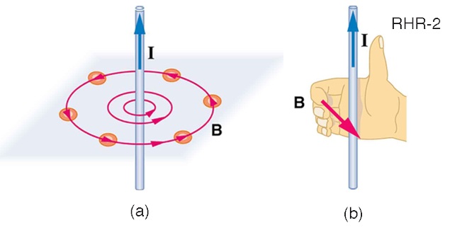
Image (modified) from University of Central Florida College Physics eBook
For a single wire use the right hand rule: thumb for current, curled fingers give the direction of the magnetic field.
For a single loop we have:
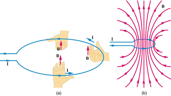
Image from University of Central Florida College Physics eBook
For a coil, however, the magnetic field inside the coil is uniform and can be concentrated using a ferrous metal core. Outside the coil it is not uniform. For a loop/coil still use the right hand, but now the fingers are used for the current direction and the thumb gives the direction of the magnetic field through the coil.
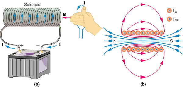
Image from University of Central Florida College Physics eBook
Lenz's Law
Lenz's law states that the induced e.m.f in a circuit is directed so that the current it drives produces a magnetic field opposing the change in magnetic flux that produced it. And if we use the right hand rule (section above) we see therefore that the induced current opposes the current that is flowing through the coil. This is why Faraday's (next section) law includes a minus sign.
Induced e.m.f produces current opposing inducing current
In simpler terms, when you try to change the magnetic environment of a circuit, the circuit responds in a way that pushes back against that change.
This means that when current is first passed through the inductor, the magnetic field is establish and for an incredibly short time, before it becomes stable, is changing. Thus a momentary EMF, opposing the EMF across the inductor, is generated.
So in a loop, magnetic force IN means current OUT And changing current IN means magnetic force OUT
Lenz's law can also be considered in terms of conservation of energy. If pushing a magnet into a coil causes current, the energy in that current must have come from somewhere. If the induced current causes a magnetic field opposing the increase in field of the magnet we pushed in, then the situation is clear. We pushed a magnet against a field and did work on the system, and that showed up as current. If it were not the case that the induced field opposes the change in the flux, the magnet would be pulled in and produce a current without any work. Electric potential energy would have been created, violating the conservation of energy.
More easily digested like this: Imagine pushing a magnet toward a loop of wire. As the magnet gets closer, the magnetic field through the loop increases. The loop responds by creating its own magnetic field that tries to oppose the magnet coming closer.
A changing magnetic field through a conductor induces a voltage. That voltage drives a current around the loop. The direction of that current is not arbitrary. It is chosen so that the magnetic field produced by the current opposes the original change in magnetic flux.
This direction rule is Lenz's law.
In an inductor, a changing current creates a changing magnetic field. That field induces a voltage in the same conductor which opposes the change in current. This is why inductors resist sudden changes in current.
Faraday's Law
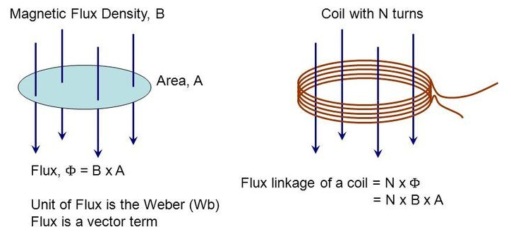
Image from Physics Stack Exchange
The flux density is
The total flux is
Where
Faraday's law says that the EMF induced is proportional to the rate of change of flux through the loop:
The
What is the constant of proportionality? It is the inductance of the coil:
Where
THUS, INDUCTORS OPPOSE CHANGES IN CURRENT
But wait a minute! We just replaced
The answer is that we can replace "rate of change of flux" with "rate of change of current" only in the special case where the flux is produced by that same current, which is what happens in self inductance.
For a coil (or any inductor), the magnetic field it produces is proportional to the current
So,
Thence we got to
In words, the rate of current change in an inductor is proportional to the voltage across it.
The Effect Of Inductance
The following animation what happens when a square voltage pulse is put across an inductor for increasing values of inductance.
FIXME? Not sure this is quite right?
We can see that there is an instantaneous change of voltage across the inductor, but that the inductor slows the increase of current: current cannot change instantaneously through an inductor.
The current through the inductor will eventually be stable, and therefore the magnetic field will become stable. We know from Faray's law that it is a changing current that generates a changing magnatic field and therefore the "back EMF".
We can also see that when the voltage is "turned off", the inductor "fights" this. The change in voltage again causes a change in magnetic field, which the inductor tries to oppose.
At the start, although the current is small, the change in current is not small, it can be quite large.
At the start, the induced back e.m.f. is limited. In a simple series RL circuit with a step DC voltage
We know how to define the two volates so we can write:
So, when voltage first goes high, because no current is flowing (as per the graphs above) the voltage across the resistor must be zero.
Therefore, at
But, here's the thing, the change in current is not zero, so we get, at the start (
If we know the inductance, we know that the rate of change of current must be, just by rearranging the above
equation (again at
As both
Reactance
This opposition to the current creating the magnetic field, as described by Lenz's law, is like a resistance, but it is not exactly resistance, even though it opposes current. Unlike resistors, which dissipate energy as heat, inductors (minus parasitics) do not dissipate energy, they store energy and return it later! I.e:
- Resistance removes energy from the circuit as heat.
- Reactance swaps energy back and forth between the source and the fields.
Reactance X is defined as a real number that measures how strongly an inductor, in this case, opposes AC at a given angular frequency.
An indictor's reactance
Where
How did we get here? We set current like so:
Then the voltage across the inductor will be:
The ratio of magnitudes gives reactance, our resistance-like quantity:
This shows that inductors have a frequency-dependent reactance, which increases with increasing frequency. So, a series inductor could be used to pass dc and low frequencies (where its reactance is small) while blocking high frequencies (where its reactance is high), for example.
Voltage Leads Current
If we say that
Then
So we are comparing:
Thus voltage leads current because the voltage cosine reaches its peak earlier in time. To know this, write one function in terms of the other:
So we are comparing:
This tells you directly that cosine is a sine shifted forward by
For inductors think ELI - Voltage leads current, or put another way current lags voltage. In the example above we note that because current is a sine wave and voltage is a cosine wave, both of the same frequency, that they are 90 degrees out of phase.
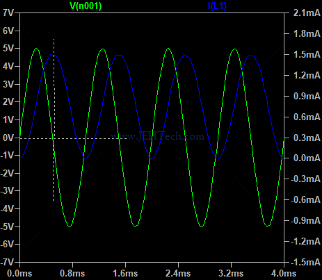
In the above the voltage and current aren't exactly 90 degrees out of phase. This is because the modelled components are non-ideal and the 90 degree phase shift is for an ideal resistor and ideal inductor, where the latter would have pure inductance etc.
This article and this article (much simpler explanation I liked it more) explain it futher.
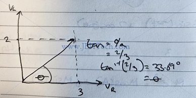
The two voltages across the resitor and inductor are a vector sum, and are not directly additive as such:
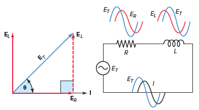
Image from Electrical Academia - RL Series Circuit
Lets take an example...
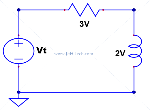
Imagine we have put an oscilloscope over the resistor and find that
We can go about solving this in two ways. The reason I show this is that I went down one route and then wondered what the phase of
Using this method I found the phase of the total voltage relative to the inductor...
Trig...
To continue we equate the above with the identity
Thus we get:
But here's a question, phase relative to what?!.
Because we have used the identitity that expresses the sum as a
That looks quite easy, but I think the maths just worked out in this example. Mostly doing it the "pure trig" way is much harder than using phasors...
Phasors...
Now lets solve it a different way, using phasors to make the maths simpler!
We can write
Argand diagram...
Turns out I could have gone even quicker and just plotted it on an argand diagram being carefull to put my reference,
in this case
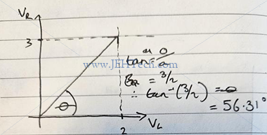
Now that was super quick!
Using this method I found the phase of the total voltage relative to the resistor...
Trig...
To continue we equate the above with the identity
Thus we get:
But here's a question, phase relative to what?!.
Because we have used the identitity that expresses the sum as a
That looks quite easy, but I think the maths just worked out in this example. Mostly doing it the "pure trig" way is much harder than using phasors...
Phasors...
Now lets solve it a different way, using phasors to make the maths simpler!
We can write
Argand diagram...
Turns out I could have gone even quicker and just plotted it on an argand diagram being carefull to put my reference,
in this case
Now that was super quick!
A Little Aside...
But.... why was current chosen as a sine and not a cosine? Well, first, the current was specified rather than the voltage because we get a simple derivative rather than an integral - a little easier I guess. Second, it doesn't matter whether we say the current is a sine or cosine as the physics wont change! Voltage will always lead current.
Lets instead say that:
Then, we get this:
It might look, if you consider the signals at time
But, we know
So, we rewrite the voltage in this case as:
So we are comparing:
Hence they are still 90 degrees out of phase, with voltage leading current (a negative phase shift means a shift to the right in time and the minus sign inverts the waveform.)
Impedance
First we need to talk about reactance and impedance.
Impedance is the full opposition to AC current and consists of resistive and reactive parts:
The reactance is the complex part, but note that reactance is not complex in itself. Reactance is a real valued quantity. The complexity appears when reactance is combined with
The complex quantity
Thus, impedance encodes both magnitude and phase information. The magnitude is:
And the angle is:
Impedance determines both how much current flows and the phase shift between voltage and current.
The angle represents the phase difference between voltage and current:
The magnitude of
Where
When we move to impedance, we need to represent both magnitude and phase. A +90 degree phase shift corresponds to multiplication by
Thats why we sometimes see
So... we have complex inductance. The phase shift is the phase shift between voltage and current. We can no longer
represent current at some time,
We have already seen that we can write this (with phase now included):
Inductors In Series
Inductors In Parallel
So, for 2 inductors in parallel:
Worked Examples
1 Find the impedance
Question: Given the circuit below, find the impedance of the inductor.
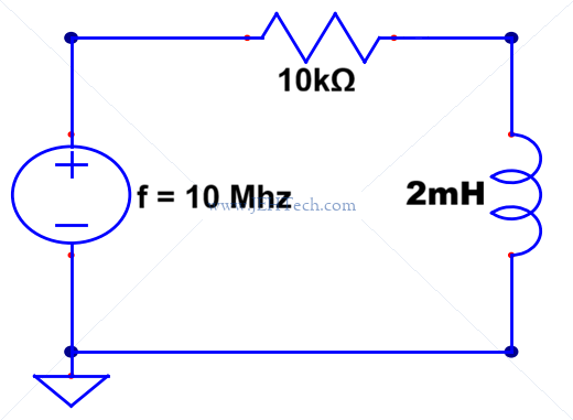
Answer:
2 Find steady state current
Question:
A circuit consists of a 12V ideal battery connected in series with a 50
Answer:
We have seen
However, when the current reaches a steady-state, we also know that
Therefore, at stead-state current, all the voltage is dropped across the resistor:
Therefore