Atmel SAM L21
Page Contents
References / useful Links
- http://www.farnell.com/datasheets/2014285.pdf
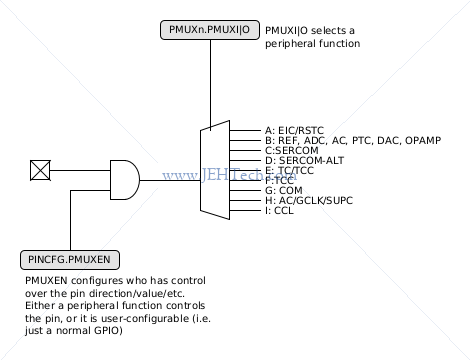
Pin Multiplexing
Event Subsystem
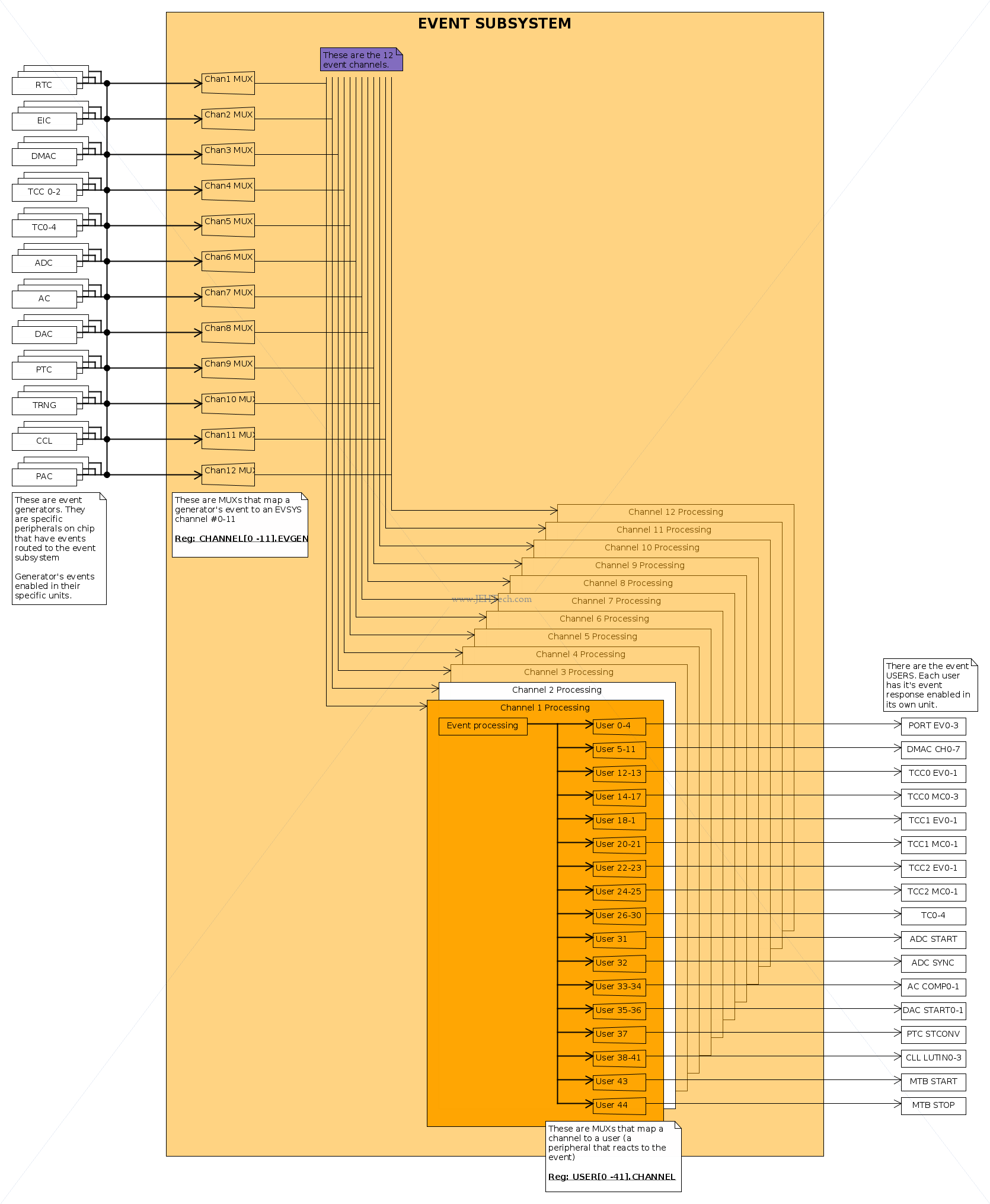
The Event System consists of several channels which route the internal events from peripherals (generators) to other internal peripherals or IO pins (users).
Initialisation
The datasheet suggests the following sequence:
-
Enable output in event generator peripheral. E.g.
RTC.EVCTRL: the RTC can generate events on overflow, comparison, and periodic intervals. -
Then confgure EVSYS: from the above diagram we see we need to configure
CHANNEL[0-11].EVGENandUSER[0-41].CHANNEL.The
CHANNEL[0-11]register can be used to set things like whether the channel runs in sleep mode, edge detection selection, path selection, event generator etc. The event generator bits choose which event generator to connect to the selected channel. For example, where we to use the RTC overflow to channel 0 we would setCHANNEL0.EVGENto the value0x03.USER[0-14].CHANNELtells us to which event user the channel output should go. I.e. settingUSER0.CHANNELdictates which channel is sent to user 0. -
Configure the event user to use the event via the
EVCTRL.EVACTin said user's registers. E.g., could count events by gettingTCto be an event user via itsTC.EVCTRL.EVACTregister. -
Enable the event in the user:
TC.EVCTRL.STARTEI.
Channel Paths
Asynchronous:
- Event from generator sent to user without event system interaction.
- No clock latency. Routing latency device dependent.
- Cannot generate interrupts.
Synchronous:
- Event generator and channel must share same generator for generic clock.
- Can generate interrupts.
- Routing latency is one
GCLK_EVSYS_CHANNEL_nclock cycle.
Resynchonized:
- Event generator and channel do not share same generator for generic clock.
- Routing latency is three
GCLK_EVSYS_CHANNEL_nclock cycles.