ARM General/Misc Notes
Page Contents
Useful
- Proceedure Call Standard for the Arm(R) Architecture
- Cortex-M4 Devices Generic User Guide
- Cortex-M4 Technical Reference Manual
- ARM Cortex-M RTOS Context Switching
- GitHub Project - minimal-c-cortex-m: A minimal Arm Cortex-M example, including semihosting...
- CPUlator
- Great collection of SVD files at platform-ststm32.git in
miscfolder.
Intro
-
Main ARM series: R for Real-time processors, A for Application processors, M for Microcontroller processors.
- Pipelines: A has long, R long/medium, M short.
- M is ultra low power and deterministic.
- MPU, NVIC, Wakeup Interrup Contrller WIC, ARM TrustZone security extensions.
- Cortex-M0(+) - Smallest most energy efficient processors. M0+ has vector relocation feature and single cycle I/O interface.
- Cortext-M23 - Similar to M0+. Better engergy efficiency and supports TrustZone extension.
- Uses the ARM-v6-M architecture.
- Cortex-M4 - Small but powerful for low-power ucontrollers. Has hardware divider and MAC instructions. Debug and trace features. DSP. SIMD instruction. Option hardware single precision float support. Uses ARM-v7-M architecture.
- Cortext-M7 - High performance. Supports double precision floating point standard. Cache and TCM.
- Instructions sets
- 32-bit ARM
- 16-bit Thumb. Introducedin 1995 as 32-bit instructions took more space and power. Both 16-bit and 32-bit instructions sets supported. 16-bit had oood code density. Supporting both impacted performance.
- 16-bit and 32-bit Thumb-2
- Introduced in 2003. Keeps the code density of the Thumb instruction set and the performance of the 32-bit set. Most processors now only support the Thumb-2 instruction set (>= M0).
-
CortexM's all use Thumb-2 instruction set.
- NO ARM instruction set support
- No Coprocessor 15: The coprocessor was used to configure the main processor. Cortex-M devices do not have this. Instead all the registers are memory-mapped to reserved regions of memory.
- Vector table is a set of addresses, not instructions.
- Typical ARM vector tables would be a table of jump instructions.
- Cortex-M23/M33 : ARMv8.
- Cortex-M3 : ARMv7-M, 3-stage pipeline.
- Mosty 32-bit instructions
- Cortex-M7 : ARMv7-M, 6 stage pipeline.
- Mosty 32-bit instructions
- Cortex-M0+ : Less than 12k gates (what the M0 "should have been").
- ARM-v6-M architecture (16-bit Thumb, except system instructions). Majority 16-bit instructions, some 32-bit instructions like
BL, for example. - 2-stage pipeline (M0 has 3-stage)
- Optional User/priviledged support
- Optional MPU with 8 regions.
- AHB-Lite master interface
- Optional low-latency I/O port. Read and writes are done in a single cycle. Address and data in one cycle. All other ARM protocols use a minimum of two cycles. Typically used for GPIO operations.
- Optional support for a WIC controller for increased power saving.
- ARM-v6-M architecture (16-bit Thumb, except system instructions). Majority 16-bit instructions, some 32-bit instructions like
- Cortex-M0/M0+ : Designed for LOW POWER.
- Majority 16-bit instructions, some 32-bit instructions like
BL, for example. - M0's are aimed at replacing PICs in the market place.
- No hardware divide.
- Hardware multiplier is optional.
- M0+ only: uTrace: use internal SRAM as a trace buffer - record the execution of the program into the trace buffer and then use debugger to access buffer.
- Von-Neumann architecture (Other Cortex-Ms use Harvard achitecture.)
- Majority 16-bit instructions, some 32-bit instructions like
- Cortex-M chips use Thumb-2 instruction set only.
- v6-M --> V7-M : ~50 instructtions --> ~200 instructions - sizeable increase.
- M4 is like an M3 with instructions for DSP - SIMD and a single-precision FPU optionally. Some operator improvement for efficiency.
- No instruction cache (except M7)
Programmers Model
- Explains the interface programmer must use to design their application on a specific processor.
- Registers:
- General Pupose
- R0-R7: Accessible to all instrunctions
- R8-R12: Accessible to a few 16-bit instructions and all 32-bit instuctions
- R13 is Stack Pointer (SP)
- Armv7-M cores have two banked versions. There are two stack pointers.
- Don't have to use both but can choose to use both.
- MSP - Main Stack (R13) (Out of reset MSP is active)
- PSP - Process Stack (priviledged)
- Points to the last entry in the stack, going down in the address range.
- R13 is an alias for the currently active stack. So if MSP is currently activated, R13 references the MSP, but if PSP is activated then R13 references the PSP. To activate one or the other, use the CONTROL register.
- Armv7-M cores have two banked versions. There are two stack pointers.
- Stack pointer must be 8 or 4 byte aligned. I.e. can only stack words or double words. But when you call a function the SP should be 8 byte aligned!
- SP points to the top of the stack.
- Stack grows downwards (full descending), i.e. the bottom of the stack is at address X and the top of the stack is at address X - STACK_SIZE. So, grows downwards means grows into lower/smaller address values as items are pushed.
- E.g. If SRAM is 0x2000_0000 to 0x2000_7FFF then at start SP is 0x2000_8000, so that the first push will be to 0x2000_7FFC (remember SP must be at least word aligned).
- Passing parameters by stack is inefficient (if more that 4 parameters to a function). Accessing stack memory, because most Cortex-M have no cache, involves memory access - costly in time and power consumption as outside bus is used. * If at all possible on your architecture, cache the stack memory!
- R14 is the Link Register (LR)
- Enables return from subroutines
- Special function for exception handling
- R15 is the Program Counter (PC): Points to the address of the code being fetched from memory at this moment.
- When jumping +1 to address when executing Thumb-2 instructions (e.g. accessing 0x1000 warite 0x1001 to PC) - its a wierd ARM thing - because ARM has hijacked bit 0 of the instruction address bus internally within the core (externally always see addredd 0x1000) and used as a way to configure the execution state of the processor. Decides which instruction set the instruction belongs to - 32-bit ARM instructions or 16-bit Thumb-2 sintructions. Bit 0 of instruction address bus is connected to T-bit of the state control register - it tells the core what type of instruction it is decoding. > The CPSR register holds the processor mode (user or exception flag), interrupt mask bits, condition codes, and Thumb status bit. The Thumb status bit indicates the processor’s current state: 0 for ARM state (default) or 1 for Thumb. -- https://www.embedded.com/introduction-to-arm-thumb
- Its of no use for Cortex-M processors as they only have Thumb-2, but, still need to jump with +1 on the address! Hey ho!
- And then... M33 then the T-bit apparently has another meaning so gets more complicated?
- Special purpose
-
Processor status (xPSR) - Combined Program Status Register - contains, in one register, the following 3 "registers":
-
Indicate the state of the core right now.
-
APSR - Application Program Status Register - Only APSR flags can be used for condition execution (
BCC,IT). In original ARM instruction set almost all instructions could be issued conditionally based on contents of APSR, but in Thumb-2 conditional execution is only supported using 16-bit branch instructionsB<c> addr.Not on M0 31 | 5 0 +--+--+--+--+--+--+--+--+--+--+--+--+--+--+--+--+--+--+--+--+--+--+--+--+--+--+--+--+--+--+--+--+ |N |Z |C |V |Q | Reserved | +--+--+--+--+--+--+--+--+--+--+--+--+--+--+--+--+--+--+--+--+--+--+--+--+--+--+--+--+--+--+--+--+ | | | | | | | | | Cumulative saturation | | | Overflow | | Carry | Zero Negative - FPSCR - Float flags (if FPU present).
31 7 6 5 4 3 2 1 0 +--+--+--+--+--+--+--+--+--+--+--+--+--+--+--+--+--+--+--+--+--+--+--+--+--+--+--+--+--+--+--+--+ |N |Z |C |V | | |DN|FZ| | Reserved | | | | | | | | +--+--+--+--+--+--+--+--+--+--+--+--+--+--+--+--+--+--+--+--+--+--+--+--+--+--+--+--+--+--+--+--+ | | vvvvv | vvvvv | | | | | Reserved ----+ | RMode | | | | | | +--- IOC AHP ----+ | | | | | +------ DZC | | | | +--------- OFC | | | +------------ UFC | | +--------------- IXC | +-------------------- Reservered +------------------------ IDC - IPSR - Contains interrupt/exception number of the current ISR.
31 5 0 +--+--+--+--+--+--+--+--+--+--+--+--+--+--+--+--+--+--+--+--+--+--+--+--+--+--+--+--+--+--+--+--+ | Reservered | ISR Number | +--+--+--+--+--+--+--+--+--+--+--+--+--+--+--+--+--+--+--+--+--+--+--+--+--+--+--+--+--+--+--+--+ -
EPSR - Contains Execution Status.
- M0
31 24 0 +--+--+--+--+--+--+--+--+--+--+--+--+--+--+--+--+--+--+--+--+--+--+--+--+--+--+--+--+--+--+--+--+ | Reservered |T | | | | | | | | | | | | | | | | | | | | | | | | | +--+--+--+--+--+--+--+--+--+--+--+--+--+--+--+--+--+--+--+--+--+--+--+--+--+--+--+--+--+--+--+--+ - M4
 31                   24                         15 14 13 12 11 10  9  8  7  6  5  4  3  2  1  0
+--+--+--+--+--+--+--+--+--+--+--+--+--+--+--+--+--+--+--+--+--+--+--+--+--+--+--+--+--+--+--+--+
|  Reservered  |     |T |  |  |  |  |  |  |  |  |  |  |  |  |  |  |  |  |  |  |  |  |  |  |  |  |
+--+--+--+--+--+--+--+--+--+--+--+--+--+--+--+--+--+--+--+--+--+--+--+--+--+--+--+--+--+--+--+--+
                |||||                            |||||||||||||||||
                ICI/IT                                ICT/IT
The EPSR is not directly accessible. Two events can modify the EPSR: 1. an interrupt occurring during an LDM or STM instruction 2. execution of the If-Then instruction.
- M0
-
APSR/IPSR/EPSR accessed as one register via xPSR. For example when an interrupt occurs, the xPSR is one of the resisters that is auto stored on the stack and looks like this:
* CONTROL: Stacks and privilege.31 24 5 0 +--+--+--+--+--+--+--+--+--+--+--+--+--+--+--+--+--+--+--+--+--+--+--+--+--+--+--+--+--+--+--+--+ |N |Z |C |V |xxxxx|T | Reserved | ISR Number | +--+--+--+--+--+--+--+--+--+--+--+--+--+--+--+--+--+--+--+--+--+--+--+--+--+--+--+--+--+--+--+--+* PRIMASK (only Arm-v7), FAULTMASK (only Arm-v7), BASEPRI: Exception handling.31 0 +--+--+--+--+--+--+--+--+--+--+--+--+--+--+--+--+--+--+--+--+--+--+--+--+--+--+--+--+--+--+--+--+ | Reservered | | | +--+--+--+--+--+--+--+--+--+--+--+--+--+--+--+--+--+--+--+--+--+--+--+--+--+--+--+--+--+--+--+--+ | | SPEL (stack def) ------+ | nPRIV -----+ ** Note **: A change requires an ISB! - PRIMASK is a 1 bit register that when set blocks all interrupts other than the NMI and hard fault. * In unprivileged mode all special registers are read only except for the APSR. The EPSR is not accessible (reads zero) in all modes. IPSR is always RO.
-
-
- General Pupose
Architecture
An architecture defines how the program execution should behave and how the debuggers interact with the processor
.
A micro-architecture defines the exact implementation details of the processor, e.g. how many pipeline stages ... etc
.
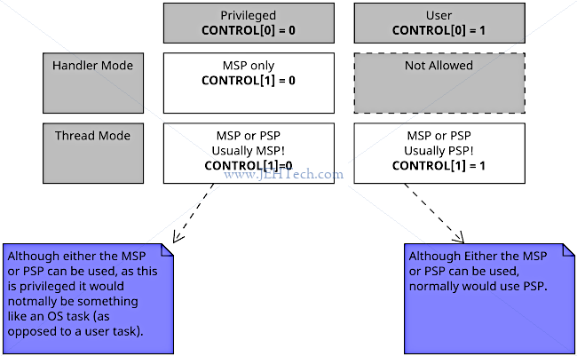
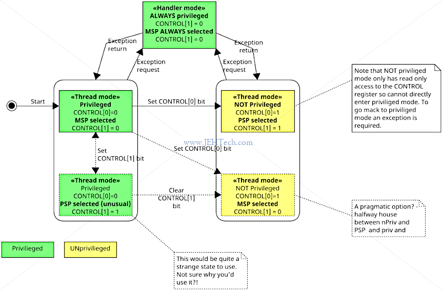
- Modes, privilege and stacks
- Handler Mode
- Entered when taking any exception.
- Always privileged.
- Always uses main stack.
- OS can run here.
- Handles exceptions.
- Processor returns to thread mode once exception processing finished.
- Always priviledged.
- Thread mode
- Execute applications.
- Processor enters thread mode (priviledged) at startup.
- CONTROL register controls whether executions is privileged or un privileged.
- Core enters thread mode out of reset.
- Typically used for user app code.
- Runs either priviliedged or unpriviliedged (should be configured by the reset handler).
- Can use either main or process stack.
- Typically uses process stack if Thread mode is unpriviledged.
- User "apps" can run here.
- On reset processor runs in thread mode.
- Handler Mode
-
If we use PSP it is because we want to use it in user mode. MSP is meant to be used by an operating system. On a simple system that does not have such a separation it would probably just use the MSP.
-
Priviledge levels:
- Unprivileged:
- Limited access to MSR (move general register to program status register (PSR)) and MRS (copy PSR to general register) instructions.
- Cannot use change-process-state (CPS) instruction.
- Cannot access sys timer, NVIC, or system control block.
- Restricted access to peripherals.
- Must use SVC instruction to make supervisor call to transfer priviledge levels.
- Privileged:
- Can use all instrutions and resources.
- Can write to CONTROL register to change privilege level.
- Out of reset you are in privileged mode.
- Unprivileged:
-
Interrupts and Exceptions
- Optimized for low latency and good interrupt performance.
- Auto save and restore of processor registers.
- Implements all ARMv7-M low latency features - this is available on the M0(+) devices too.
- Late arrival, tail-chaining, lazy FPU stacking, ICI bits for load/store multiple operations.
- Aggressive flushing of multi-cycle operations in pipeline.
- To enable interrupt processing to start quickly.
- Applies to all DEV/SO loads/stores that have bit vee started on the bus.
- Avoids bursts on the bus for DEV/SO load/store multiples - may reduce bus performance.
- Core includes Nested Vectored Interrupt Controller (NVIC).
- Interrupt latency:
- Typically 12 cycles.
- 15+ cycles for M0.
- Optimized for low latency and good interrupt performance.
-
Power Management
- Mostly SoC dependant.
- Sleep modes:
- SLEEPING.
- DEEPSLEEP.
- Controlled by system control reigsters.
- Is software programmable (just states an intention - the job to actually go deep sleep is left to the SoC implementor to do).
- WIC-based DEEPSLEEP.
- 2 outputs: 1 to say "I am sleeping" and 1 to say "I am DEEP sleeping" so the SoC can see its state.
- WFI, WFE and SEV instructions (wait fo rinterrupt/event and send event).
- If you execute these the core goes into standby state an asserts the sleep signals so the SoC can see its state.
- Sleep On Exit.
- Sleep immediately on return from last ISR.
- System clock is gated in sleep modes.
- Sleep signal is exported allowing external systemn to be block gated.
- NVIC interrupt interface stays awake.
- Wake-Up Interrupt Controller (WIC).
- Optional external wak-up detector allows core to be fully powered down.
- Effecting with State-Retention Power Gating (SRPG) methodology.
Instruction Set
- WARNING:
nopnot guaranteed to waste a cycle!!!! usemv r0, r0instead. TODO - Sync
- WARNING DMB only works for one bus - 2 load/stores on 2 different busses do not have order of execution segregated by DMB as it only focuses on one bus and does not work across busses.
- DSB is stricter than DMB - not just load/stores but intructions too - no futher instructions may complete execution or change interrupt masks until the Memory Barrier instruction completes. Including implicit operations - e.g. a cache controller refreshing its contents etc. Applies to multiple busses and broadcasts to other cores in the cluster.
- See https://developer.arm.com/documentation/dai0321/a/?lang=en
ABI
From aapcs32/aapcs32.rst:
Core Registers
| Register | Alias | Special | Role in the procedure call standard |
| r15 | PC | The Program Counter. | |
| r14 | LR | The Link Register. | |
| r13 | SP | The Stack Pointer. | |
| r12 | IP | The Intra-Procedure-call scratch register. | |
| r11 | v8 | FP | Frame Pointer or Variable-register 8. |
| r10 | v7 | Variable-register 7. | |
| r9 | v6 | SB TR | Platform register or Variable-register 6. The meaning of this register is defined by the platform standard. |
| r8 | v5 | Variable-register 5. | |
| r7 | v4 | Variable-register 4. | |
| r6 | v3 | Variable-register 3. | |
| r5 | v2 | Variable-register 2. | |
| r4 | v1 | Variable-register 1. | |
| r3 | a4 | Argument / scratch register 4. | |
| r2 | a3 | Argument / scratch register 3. | |
| r1 | a2 | Argument / result / scratch register 2. | |
| r0 | a1 | Argument / result / scratch register 1. |
From the AAPCS, 5.1.1:
- r0-r3 are the argument and scratch registers; r0-r1 are also the result registers - clobbered across a function call
- r4-r8 are callee-save registers - preserved across a function call
- r9 might be a callee-save register or not (on some variants of AAPCS it is a special register)
- r10-r11 are callee-save registers
- r12-r15 are special registers
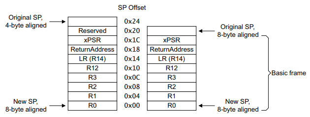
Stack
The ARM stack is fully descending. Descending means that it starts at a high address and each push decrements the stack pointer.
In a Full stack, the stack pointer points to the topmost item in the stack, i.e.,the last item pushed into it. When pushing data into a Full stack, the stack pointer is first adjusted to reflect its new location and then the data is stored in the stack at the address in the stack pointer.
The stack pointer must normally be 4-byte aligned, except at a "public interface", when it should be 8 byte, or double-word, aligned. A "public interface" consists of any externally accessible functions offered by a library or component. I.e., when enterying any function, the stack should always start off 8-byte aligned.
The stack frame is described in Figure B1-3 of the ArmV7 Exception Model like so (when no FP registers saved):
Exceptions / Interrupts
References
NVIC Enabled Interrupt
The interrupts are grouped in groups of 32, where NVIC_ISER[0] is for vectors numbered 0 through 31, NVIC_ISER[1] 32 through 63, and so on. In the the vendor's CMSIS package,
there is likely the type IRQn_Type. The vectors 0 and above, map directly to the NVIC_ISRx register.
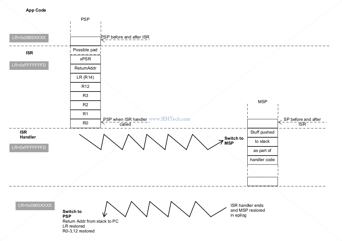
Stacking
Stacking is done by the Cortex-M for you and involves saving the current state of the processor so that the interrupted program can be resumed after the interrupt is serviced.
- Uses the fore ground stack, which can be either the MSP or PSP, to save the pre-interrupt state of the CPU (unless the exception is a tail-chained or a late arriving exception).
- Uses a micro-coded entry/exit mechanism whereby the the hardware itself will do things like save the processor context etc. Thus, when your ISR code executes, the state of the task executing just before the exception has already been saved to the active stack. Makes interrupt handling simpler.
- Reads ISR address from vector table.
- Link register modified for interrupt return.
- First instruction of ISR executed. (approx. 11 - 12 cycles delay for this to happen).
- It is executed in handler mode using the main stack pointer.
Cortex M0
https://community.arm.com/arm-community-blogs/b/embedded-blog/posts/cutting-through-the-confusion-with-arm-cortex-m-interrupt-priorities https://interrupt.memfault.com/blog/arm-cortex-m-exceptions-and-nvic https://developer.arm.com/documentation/ddi0403/d/System-Level-Architecture/System-Level-Programmers--Model/ARMv7-M-exception-model/Stack-alignment-on-exception-entry
TODO/FIXME - formatting is broken!
-
If the program being interrupted is not an interrupt and the PSP is being used, use the PSP, otherwise use the MSP. In other words, the PSP is only used when interrupting a thread-mode program already using the PSP.
-
Push onto selected stack, in the following order:
R0-R3,R12,LR, return-address,xPSR. The return address depends on the exception type:- NMI - address of the next instruction to be executed.
- HardFault (precise) - the address of the instruction causing fault.
- HardFault (imprecise) - address of the next instruction to be executed.
- SVC - address of next instruction after SVC.
- IRQ - address of next instruction after interrupt.
-
Set the LR to special magic value that is intercepted on exception exit.
-
If the program being interrupted is an interrupt:
LR = 0xFFFFFFF1: Return to Handler Mode. Exception return gets state from the Main stack. On return execution uses the Main Stack. -
Else if the MSP is being used by the thread mode program:
LR = 0xFFFFFFF9: Return to Thread Mode. Exception return gets state from the Main stack. On return execution uses the Main Stack.- Else
LR = 0xFFFFFFFFD: Return to Thread Mode. Exception return gets state from the Process stack. On return execution uses the Process Stack.
-
-
Prepare to jump to service handler
- Change current mode to handler mode
- Change stack to MSP
- Get address of service handler based on exception number
- Jump to exception handler.
Unstacking
Unstacking is the opposite of stacking and occurs when the last interrupt service routine returns. It restores the state of the interrupted program and resumes it, or possibly instead puts the processor to sleep.
Cortex-M0
Stack Unwinding
Why Are Frame Pointers "Deprecated"
In a word inefficiency - waste a register and have to push/pop that register on every function call, when a function call doesn't need it... it knows what it did to the stack so can undo it on a return. Only needed the FP for stack unwinding, which is relatively rare. Hence the move to exception handling tables. [Ref].
According to an analysis by Mel Gorman, using frame pointers added overhead of up to 5-10% in some memory management related benchmarks.
[Ref].
PREL31
- TLDR; It's just a 31-bit signed offset relative to a location.
-
PREL31stands for "Positive RELative 31-bit," which describes a specific way of encoding relative offsets. It is used in ARM architecture to represent a 31-bit signed relative offset to a target address- Can be used to allow Position Independent Code (PIC): the program code to run from any memory address, as it uses offsets relative to the program counter rather than absolute addresses.
- Also used for static linking:
Relocation information is used by linkers in order to bind symbols and addresses that could not be determined when the initial object was generated.
- When a linker encounters an R_ARM_PREL31 relocation, it needs to modify the instruction to include a relative offset to the target symbol. This offset is calculated based on the address of the instruction itself and the address of the target symbol.
- Uses:
- Could be for function calls to functions located a fixed offset relative to the current instruction.
- Could be for data that is located at a fixed offset relative to the current instruction.
-
From aaelf32, the definition of the encoding is
PREL31 = (((S + A) | T) - P) & 0x7FFFFFFF, whereS= Address of symbolA= Addend for relocationP= Address of place being relocated toT=1ifSis a function and the Thumb instruction set is being used,0otherwise.- For example, when modifying an instruction with a PREL31 offset,
Pis the instructions address andSis the symbol being referenced, and I guessAis0. From the PREL31 value, the offset is calculated and the instruction's immediate value is set to hold this offset.- Lets say the instruction is at
0x1500and the function is at0x2000. From the above we calculate((0x2000 + 0x0) - 0x1500) & 0x7FFFFFFFto get0xB00. - Lets say the instruction is at
0x2000and the function is at0x1500. From the above we calculate((0x1500 + 0x0) - 0x2000) & 0x7FFFFFFFto get0x7FFFF000, which because this is a signed 31-bit number, is-2816, or -0xB00.
- Lets say the instruction is at
To understand this better, especially the addend, which confused me a little, one has to look at relocations.
The article Relocations: Fantastic Symbols But Where To Find Them is a really great (bloody amazing) read with many good references available within.
So why an "addend"? For example, an addend might be required to compensate for PC bias. If a jump or symbol address is PC relative, an addend must be used because the PC will be ahead of the currently executing instruction, but the offset is relative to the currently executing instruction. Therefore the addend would subtract X bytes to use the PC as it was the the instruction to which the offset refers:
Relocation information is used by linkers in order to bind symbols and addresses that could not be determined when the initial object was generated ...
A binary file may use REL or RELA relocations or a mixture of the two ... If the relocation is pc-relative then compensation for the PC bias (the PC value is 8 bytes ahead of the executing instruction in Arm state and 4 bytes in Thumb state) must be encoded in the relocation by the object producer.
In the unwind code, even in GCCs own code, the addend for PREL31 encoding appears to be assumed to be zero.
Exception Index Table & Handling Table
Exception Index Table
Exception-handling table entries have a variable size. A handling table entry is found by searching a table of index entries. To support binary search, the index table must consist of contiguous fixed-size entries, each of which identifies a function start address, with the entries ordered by increasing function start address
-- EHABI32.
Exception Handling Table (EHT)
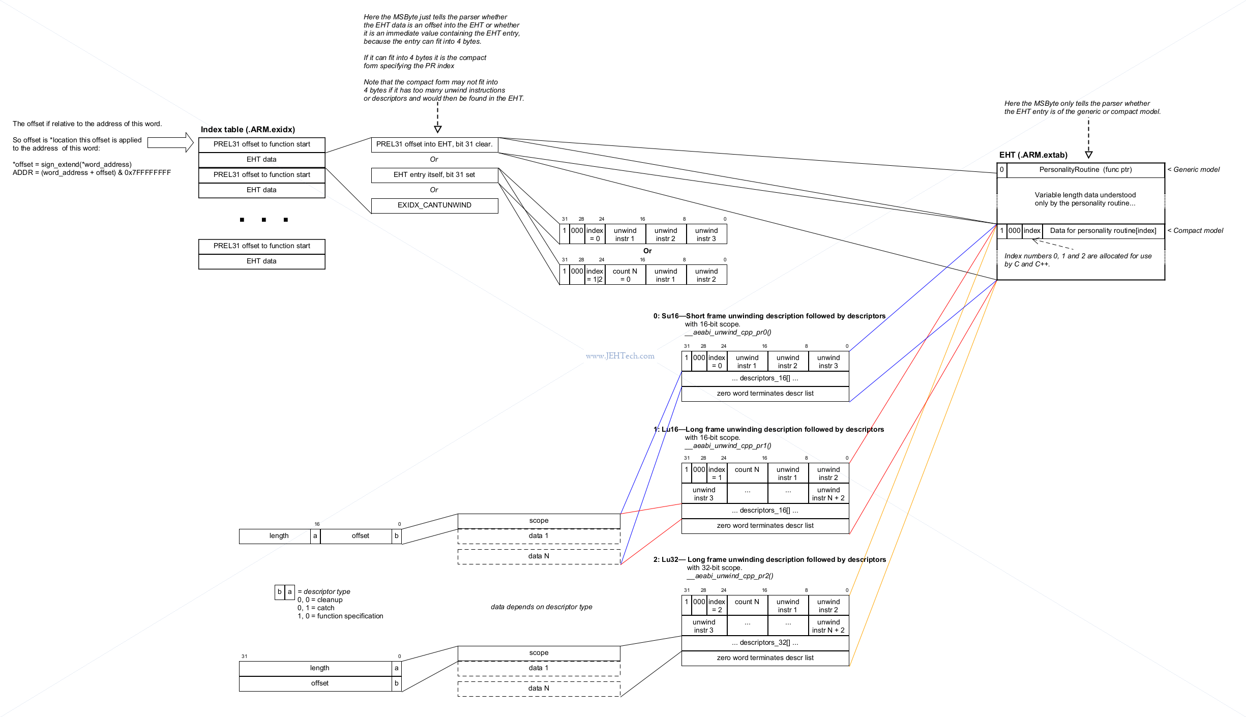
The exception-handling table (EHT) contains one entry for each non-leaf function that may need to be unwound ... A table entry has a variable size. It encodes ... the actions required to propagate an exception through the function ... How to unwind a stack frame associated with the function ... In some usefully common cases, a handling table entry contains so little information that it’s content can be packed directly into the index table entry
-- EHABI32.
The format of the entries is shown in the image below.
Unwinding The Stack
Unwinding the stack is done in two phases:
- The stack is virtually unwound looking for a propagation barrier.
- The stack is really unwound and cleanups are run
A virtual register set is a buffer area used to hold copied of the real machine registers and other relevant machine state so that, for example, the first phase can search for a propogation barrier without actually modifying the real machine state. It is used in stack unwinding as an abstraction of the processor's register state during an exception and plays a critical role in decoding, simulating, and restoring the state of the processor during stack unwinding.
... TODO - the rest ... I don't have to look at this any longer so leaving it here for now ...
Context Switching
References
- PendSV+SVC on Cortex M
- ARM Cortex-M RTOS Context Switching
- FreeRTOS
port.cSource Code For Cortext-M0
PendSV
PendSV is generally used for context switching because, unlike the SVC exception, which is synchronous (happens as soon as the SVC instruction is encountered), the PendSV exception is asynchronous and once pended will only execute when no other exceptions are pending. The main advantage is that it can be pended from an ISR.
How FreeRTOS Does It
Very much based on the article ARM Cortex-M RTOS Context Switching.
The FreeRTOS xPortPendSVHandler() function in the port.c code for the Cortex-M0, which I'm reading up on because it is the simplest of the Cortex-M's, is as follows (rev 83083a8a1):
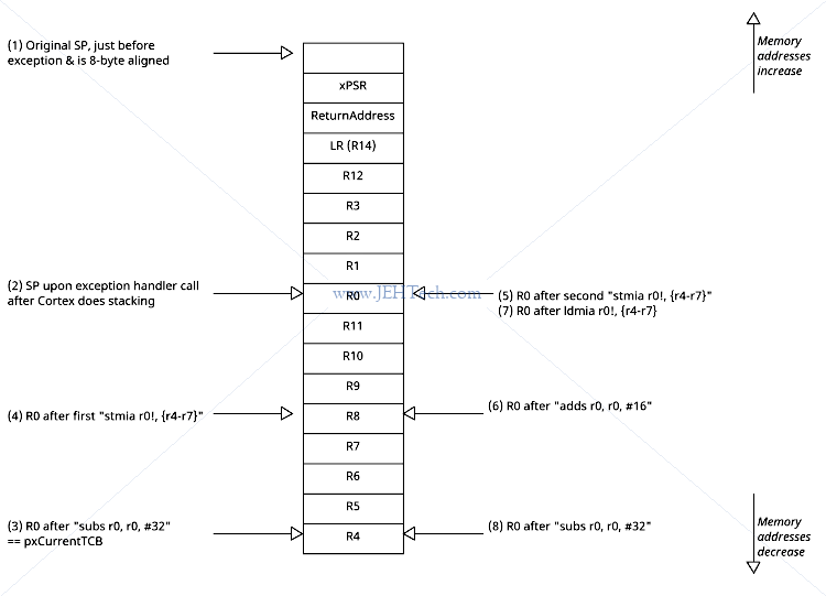
Each NOTE x in the explanation refers to the diagram below the function excerpt.
| Line of code | Explanation |
mrs r0, psp | Copy the PSP stack register into R0. NOTE 2 |
ldr r3, pxCurrentTCBConst | Load pointer to pointer to TCB into R3. pxCurrentTCBConst is defined at the end of
this function and is equivalent to TCB_t **pxCurrentTCBConst = &pxCurrentTCB |
ldr r2, [r3] | Dereferences pointer above to get pointer to TCB. R2 = *pxCurrentTCBConst == pxCurrentTCB |
subs r0, r0, #32 | Reserve 32 bytes (8 32-bit words) on the PSP stack. NOTE 3 |
str r0, [r2] | Do *(uint32_t *)pxCurrentTCB = R0 = PSP - 32. The pointer memory location
*(uint32_t *)pxCurrentTCB is the first member of the TCB_t struct, which is a
pointer to the location of the last item placed on the tasks stack. The member
pointer is named volatile StackType_t * pxTopOfStack in tasks.c. Thus, this really
does pxCurrentTCB->pxTopOfStack = PSP - 32. |
stmia r0!, {r4-r7} | Push registers 4 through 7 into pxCurrentTCB->pxTopOfStack, taking up the 4
words reserved two lines above, updating R0 afterwards. The Cortex micro code will have saved registers R0-R3, R12, the LR, return address and xPSR registers to the stack for us. Here the pendSV must be assumed to execute from thread mode, otherwise we would have to figure out which stack was selected before the interrupt. NOTE 4 |
mov r4, r8 | Move the high-registers (not auto-saved by the Cortex on exception) into the low registers just
put on the stack so that the high-registers can then be put onto the stack - stmia
can only use the low-registers. |
mov r5, r9 | |
mov r6, r10 | |
mov r7, r11 | |
stmia r0!, {r4-r7} | Same again, save registers 8 through 11 into the reserved area on the PSP. NOTE 5 |
push {r3, r14} | Because this is interrupt service routine code, the selected stack is the MSP. So
this pushes registers r3 (pxCurrentTCBConst) and r14 (the LR) onto the MSP. |
cpsid i | DISABLE INTERRUPTS |
bl vTaskSwitchContext | Do the task switching atomically |
cpsie i | ENABLE INTERRUPTS |
pop {r2, r3} | R2 gets pxCurrentTCBConst saved 4 lines above, and R3 gets the LR |
The pxCurrentTBC pointer most likely now points to a different thread stack so restores now restore the context for the next thread to be run!!! | |
ldr r1, [r2] | R1 = *pxCurrentTCBConst |
ldr r0, [r1] | R0 = **pxCurrentTCBConst == pxCurrentTCB->pxTopOfStack |
adds r0, r0, #16 | Add 16 bytes (4 32-bit words) to pxCurrentTCB->pxTopOfStack` so that the saved high
registers can be loaded into the actual registers again. NOTE 6 |
ldmia r0!, {r4-r7} | Restore the high registers into the low registers as stmia
can only use the low-registers. NOTE 7 |
mov r8, r4 | Move the low registers into high registers, thus completing the restoration of the high registers |
mov r9, r5 | |
mov r10, r6 | |
mov r11, r7 | |
msr psp, r0 | Move R0 into PSP. This is the value of the SP as it was when the exception handler routine was entered. |
subs r0, r0, #32 | Point back to the low registers that were saved previously. NOTE 8 |
ldmia r0!, {r4-r7} | Restore them |
bx r3 | |
.align 4 | |
pxCurrentTCBConst: | Equivalent to TCB_t **pxCurrentTCBConst = &pxCurrentTCB |
Generated from free_rtos_contexxt_switch_stacks.ufx
From the image of the stack above it is easier to see that the context switch is performed between notes 5 and 6. Hence, for steps 6 onwards, a different context is being restored... hence the context switch!
Setup GCC (Ubuntu)
- Download the toolchain from the ARM website. The the time of writing (Dec 2022) I downloaded 11.3.Rel1 as
arm-gnu-toolchain-11.3.rel1-x86_64-arm-none-eabi.tar.xz. - Extract this to a directory of your choice. You could use
/usr/share, or/opt/gcc-arm-none-eabifor example. The following instructions were taken from here.sudo mkdir /opt/gcc-arm-none-eabi sudo tar xf arm-gnu-toolchain-11.3.rel1-x86_64-arm-none-eabi.tar.xz --strip-components=1 -C /opt/gcc-arm-none-eabi echo 'export PATH=$PATH:/opt/gcc-arm-none-eabi/bin' | sudo tee -a /etc/profile.d/gcc-arm-none-eabi.sh source /etc/profile - Add the
binfolder under your installation directory to thePATHenvironment variable.
Pre Ubuntu 23
NOTE the following steps do not work in Ubuntu 23.
- If you see the following when running GDB, install ncurses using
sudo apt install -y libncursesw5.opt/gcc-arm-none-eabi/bin/arm-none-eabi-gdb: error while loading shared libraries: libncursesw.so.5: cannot open shared object file: No such file or directory - If after installing ncurses it moans about Python, you don't have Python (3.8) installed! On Linux, Arm GNU toolchain provides GDB with Python support. It requires installation of Python 3.8 [Ref]. To install Python 3.8 specifically:
sudo add-apt-repository -y ppa:deadsnakes/ppa
sudo apt install -y python3.8
Ubuntu 23 and later
Ubuntu 23 has removed the libncurses5 and libncursesw5 packages because they were removed in
upstream Debian [Ref].
To install the the packages you can use the insecure package repository lunar-security by
adding the following to your /etc/apt/sources.list file [Ref][Ref]:
deb http://security.ubuntu.com/ubuntu lunar-security main universe
Then do
sudo apt update
sudo apt install -y sudo apt-get install libncurses5 libncursesw5
sudo apt --fix-broken install
Then use Python 3.8.18 as required by the ARM GDB, it is easiest to use PyEnv, the following taken verbatim from [Ref]
pyenv install 3.8.18
sudo mkdir -p /usr/local/bld-tools
sudo ln -s $PYENV_ROOT/versions/3.8.18 /usr/local/bld-tools/bld-tools-virtual-env
GDB should now work!
Setup A Minimal (WSL) Development Environment
Install WSL
- Enable WSL (if not already enabled). Open PowerShell as Administrator and run
wsl –install. - Install a fresh Ubuntu distribution and give it a name:
wsl --install -d Ubuntu --name Ubuntu_MyNewDistro - Start new distro:
wsl -d Ubuntu_MyNewDistroand follow the following instructions...
Setup Basic System Prerequisits
sudo apt update
sudo apt-get install -y build-essential \
                        make \
                        libssl-dev \
                        libtool \
                        libusb-1.0-0-dev \
                        m4 \
                        pkg-config \
                        autoconf \
                        automake \
                        texinfo \
                        libhidapi-dev
Setup CMake
mkdir -p /tmp/build
git clone https://github.com/Kitware/CMake.git /tmp/build/cmake
pushd  /tmp/build/cmake
git checkout v3.30.5
mkdir build && cd build
../bootstrap --prefix=/usr --parallel=$(nproc --all)
make -j$(nproc --all)
sudo make install
popd
rm -rf /tmp/build
If you are using link time optimisations -flto and building some parts of the program into static libraries, the gcc ar tool needs this:
# Needed for AR to support LTO - link time optimisation
set(CMAKE_C_ARCHIVE_CREATE "<CMAKE_AR> qc --plugin /opt/gcc-arm-none-eabi/libexec/gcc/arm-none-eabi/12.3.1/liblto_plugin.so <TARGET> <LINK_FLAGS> <OBJECTS>")
Setup GCC Cross Compiler
mkdir -p /tmp/build
wget -q -O "/tmp/build/arm-gnu-toolchain.tar.xz" "https://developer.arm.com/-/media/Files/downloads/gnu/12.3.rel1/binrel/arm-gnu-toolchain-12.3.rel1-x86_64-arm-none-eabi.tar.xz"
sudo mkdir -p /opt/gcc-arm-none-eabi
sudo tar -xf /tmp/build/arm-gnu-toolchain.tar.xz --strip-components=1 -C /opt/gcc-arm-none-eabi
rm -rf /tmp/build
echo 'export PATH=$PATH:/opt/gcc-arm-none-eabi/bin' | sudo tee -a /etc/profile.d/gcc-arm-none-eabi.sh
Setup OpenOCD
mkdir -p /tmp/build
git clone https://github.com/openocd-org/openocd.git /tmp/build/openocd
pushd  /tmp/build/openocd
git checkout v0.12.0
./bootstrap
mkdir build && cd build
../configure --prefix=/opt/openocd --enable-stlink --enable-internal-libjaylink --enable-jlink --enable-cmsis_dap --enable-remote-bitbang
make -j$(nproc --all)
sudo make install
popd
rm -rf /tmp/build
echo 'export PATH=$PATH:/opt/openocd/bin' | sudo tee -a /etc/profile.d/gcc-arm-none-eabi.sh
Misc Snippets
Am I In An ISR?
bool in_isr(void) {
    return (SCB->ICSR & SCB_ICSR_VECTACTIVE_Msk) != 0;
}
Is Debug Probe Attached?
bool is_debugger_attached(void) {
    /* When a debugger attaches it should set one of these bits (note assumes a debugger that
     * supports this is used, check your probe does this!) */
    return (DBGMCU->CR & (DBGMCU_CR_DBG_STOP | DBGMCU_CR_DBG_STANDBY)) != 0;
}