Mobile Comms Notes
Page Contents
Terminology
| Acronym | Meaning |
|---|---|
| APN | Access Point Name An Access Point Name (APN) is a gateway between a GSM, GPRS, 3G or 4G mobile network and another computer network, frequently the public Internet. A mobile device making a data connection must be configured with an APN to present to the carrier. An MNO can have multiple APNs, each serving as a distinct entry point to the other computer network. They might have several APNs for service differentiation, roaming, private networks etc... Here's a site that gives a list of a whole load of APNs. One can see that O2, for example, have several APNs, some for pay-and-go contracts, others offering faster access etc. |
| BTS | Base Transceiver System - aka Base Station |
| CDMA | Code Division Multiple Access |
| EDGE | Enhanced Data Rate for GSM Evolution |
| EPC | Evolved Packet Core: 4G core network |
| EUTRAN | Evolved Universal Terrestrial Radia Access Network: 4G access network - combination of E-UTRA, UE and Node-B or eNodeB |
| EUTRA | E-UTRA is the air interface of LTE |
| EVDO | EVolution Data optimized |
| GGSN | Gateway GPRS Support Node |
| GPRS | General Packet Radio Service |
| GSM | Global Systems for Mobile |
| HSPA | High Speed Packet Access |
| HSPA+ | Evolved High Speed Packet Access |
| ICCID | Integrated Circuit Card Identifier Identifies the chip of each SIM card. |
| IMEI | International Mobile Equipment Identity Think MAC address of slot SIM is inserted into |
| IMSI | International Mobile Subscriber Identity Unique identifier assigned to every SIM |
| LAI | Local Area Identity |
| LTE | Long Term Evolution (of mobile networks) |
| MCC | Mobile Country Code For example the UK MCC is 234 [See Mobile Country Codes (MCC) and Mobile Network Codes (MNC)] |
| ME | Mobile Equipment. The physical UE consisting of one of more Mobile Termination (MT) and one or more Terminal Equipment (TE). |
| MNC | Mobile Network Code A unique ID specific to a mobile operator network [See Mobile Country Codes (MCC) and Mobile Network Codes (MNC)] |
| MO | Mobile Originated (service) |
| MS | Mobile Station: your phone |
| MSC | Mobile Switching Centre: core part of the GSM/CDMA network system |
| MSISDN | Mobile Station International Subscriber Directory Full mobile number with country code and all prefixes. |
| MSRN | Mobile Station Roaming Number [See this article]. |
| MT | Mobile Termination (MT) A component of the Mobile Equipment (ME) performing functions specific to management of the radio interface. The R interface between TE and MT uses the AT command set. The IMEI code is attached to the MT. I.e., this is, for example, the UBlox module. |
| NR | New Radio |
| PDN | Public Data Network |
| PSM | Power Saving Mode |
| SGSN | Serving GPRS Support Node |
| TAU | Tracking Area Updating period |
| TE | Terminal Equipment (TE) Communications equipment at either end of a communications link, used to permit the stations involved to accomplish the mission for which the link was established. |
| UE | User Equipment. Any device used by an end-user to communicate. The UE consists of the Mobile Equipment (ME) and the Universal Integrated Circuit Card (UICC). |
| UMTS | Universal Mobile Telecommunications System |
| UTRAN | Universal Terrestrial Radia Access Network: 3G access network |
Other useful nomenclature is the term "bearer", which refers to the underlying network technology that carries the data traffic between the mobile device and the network infrastructure. The term "bearer" is often used in the context of APN settings to specify which type of network technology or protocol should be used for data communication.
Good Links
Different Mobile Comms Standards
| Standards | Technology | SMS | Voice Switching | Data Switching | Data Rates | |
|---|---|---|---|---|---|---|
| 1G | AMPS, TACS | Analog | No | Circuit | Circuit | N/A |
| 2G | GSM, CDMA, EDGE, GPRS | Digital | Yes | Circuit | Circuit / Packet (1) | GSM ~22.8Kpbs CDSM ~14.4 Kbps (single channel) GRPS ~50Kbps EDGE ~150Kbps |
| 3G | UTMS, CDMA2k, HSPA, EVDO | Digital | Yes | Circuit | Packet | UMTS/HSPA ~10Mbps UMTS/HSPA+ ~20Mbps |
| 4G | LTE, LTE advanced, IEEE 802.16 (WiMax) | Digital | Yes | Packet | Packet | LTE 20-50Mbps LTE advanced ~1Gbps |
| 4/5G | LTE-M (aka Cat-M1), NB-IoT (aka Cat-NB1) | Digital | ? | ? | ? | ? |
| 5G | Digital | Yes | Packet | Packet | ~20 Gbps | |
| [Ref] |
(1) GPRS is a packet-switched network and GSM is a circuit-switched network [Ref]
See:
- Difference Between GSM and GPRS)
- What are phone bands (GSM, CDMA) and why do they matter?
- What is EDGE (Enhanced Data Rate for GSM Evolution)?
Notes:
- GSM = Global Systems for Mobile
- Standard bearer of 2G tech,
- Introduced Simple Messaging Service (SMS),
- Circuit switched,
- Can make voice calls and transmit data at the same time,
- Most widely used standard (CDMA is US and Asia)
- GPRS = General Packet Radio Service
- Upgrade to GSM: Standard bearer of 2.5G tech
- Packet switched,
- Introduced Multimedia Messaging Service (MMS),
- Can make voice calls and transmit data at the same time.
-
EDGE = Enhanced Data Rate for GSM Evolution
- Improves upon the GSM/GPRS family: higher bit-rates per radio channel: 2.75 tech.
-
CDMA = Code Division Multiple Access
- Can not make voice calls and transmit data at the same time,
- GSM is widely used across the world, CDMA is mostly only common in the US/Asia
-
UMTS = Universal Mobile Telecommunications System
- Fully compatible with GSM, but
- Required upgrades to existing 2G networks (whether GSM, GPRS or EDGE) as UMTS uses different access technology (WCDMA) - new base stations required.
-
HSPA = High Speed Packet Access
- Tech used to enhance UMTS to improve data rates.
- Combination of HSUPA (High Speed Uplink Packet Access) and HSDPA (High Speed Downlink Packet Access)
- "3G+" or "H" icon on phone.
- HSPA+ = Evolved High Speed Packet Access
- EVDO = EVolution Data optimized
- Used in CSMA networks.
- Equivalent in GMS/UMTS networks is HSPA.
- LTE = Long Term Evolution (of mobile networks)
- 4G
-
NR = New Radio
- 5G
-
Uplink v.s. Downlink
- Uplink is connection from Mobile Station (MS), i.e., your phone, to the Base Station, a.k.a. Base Transceiver System (BTS)
- Downlink is BTS to MS comms.
- MS uses full duplex comms.
-
A combination of FDMA and TDMA is used to allow a BTS to communicate with many MS: The channels, split by frequency, are also time divided.
-
FM Frequency Modulation was 1G. All later technologies used different methods.
- FSK - Frequency Shift Keying
- PSK - Phase Shift Keying
- QPKS - Quadrature PSK
- QAM - Quadrature Amplitude Modulation - varies both amplitude and phase to get more bits per symbol.
European Commission has good infographic:
SIM and Phone Identifiers
See Difference Between IMEI, IMSI, ICCID And MSISDN Numbers By Adnan Ghayas.
| Acronym | Meaning | Linked to | Format | Description |
|---|---|---|---|---|
| IMEI | International Mobile Equipment Identity | Phone | 15 numbers | Unique identifier assigned to every cellular device for each of its SIM slots. |
| IMSI | International Mobile Subscriber Identity | SIM | 15 numbers (1) | Unique identifier assigned to every SIM card. |
| ICCID | Integrated Circuit Card Identifier | SIM | ~20 numbers (2) | Identifies the chip of each SIM card. |
| MSISDN | Mobile Station International Subscriber Directory | SIM | Full mobile number with country code and all prefixes. |
(1) Format is CCCNNIIIIIIIIII, where C (the first 3 digits) are the mobile country code, N (the next 2 digits) are the mobile network code and the last 10 digits, I, are the Mobile Subscriber Identification Number (MSIN), which the carrier uses to identify a mobile and is the last part of the IMSI. The mobile network may use a temporary IMSI called TMSI (Temporary Mobile Subscriber Identity) instead of IMSI to ensure the subscriber's confidentiality
.
(2) Usually 19 or 20 digits. Although ITU-T E.118 says that the maximum length of the visible card number ... shall be 19 characters
, some vendors do use 20 characters (e.g. Twilio). Format is similar to II-CC-SS-UUUUUUUUUUUUL, where I is the industry code, C is the country code, S is the issuer's code, and U is the unique identifier for the SIM and 'L' is the Luhn check digit. See ETSI TS 102 221 v17.3.0, which refers to ITU-T E.118. The length of the country code (C) is variable: 1 to 3 digits. The issuer identity (S) is also variable, but [with] a fixed number of digits within a country or world zone where appropriate
. Same for the unique identifier (U).
The industry code differentiates a SIM from other types of chip cards, for example, a credit card. A SIM card will always start with the numbers 89, for example [Ref].
IMSI, MMC and MNC
ITU-T E.212
The International Telecommunication Union (ITU) Recommendation ITU-T E.212 - The international identification plan for public networks and subscriptions defines:
3.2 international mobile subscription identity (IMSI): The IMSI is a string of decimal digits, up to a maximum length of 15 digits, which identifies a unique subscription. The IMSI consists of three fields: the mobile country code (MCC), the mobile network code (MNC), and the mobile subscription identification number (MSIN).
3.3 mobile country code (MCC): The MCC is the first field of the IMSI and is three digits in length and identifies a country. The Director of TSB may assign more than one MCC to a country. MCCs in the 90x range are non-geographic MCCs (country-agnostic) and are administered by the Director of TSB.
3.4 mobile network code (MNC): The MNC is the second field of the IMSI, it is two or three digits in length and is administered by the respective national numbering plan administrator. MNCs under MCC ranges 90x are administered by the Director of TSB. The MNC, in combination with the MCC, provides sufficient information to identify the home network.
Together with:
5 Considerations The considerations that form the basis for this international identification plan for networks and subscriptions are as follows:
c. The MNC consists of 2 or 3 digits and the length of the MNC is a national matter.
3GPP TS 23.003 / ETSI TS 123 003
3GPP TS 23.003 / ETSI TS 123 003 define:
2.2 Composition of IMSI IMSI is composed of three parts:
Mobile Country Code (MCC) consisting of three digits. The MCC identifies uniquely the country of domicile of the mobile subscriber;
Mobile Network Code (MNC) consisting of two or three digits for GSM/UMTS applications. The MNC identifies the home PLMN of the mobile subscriber. The length of the MNC (two or three digits) depends on the value of the MCC. A mixture of two and three digit MNC codes within a single MCC area is not recommended and is outside the scope of this specification.
Mobile Subscriber Identification Number (MSIN) identifying the mobile subscriber within a PLMN. The National Mobile Subscriber Identity (NMSI) consists of the Mobile Network Code and the Mobile Subscriber Identification Number.
together with:
2.3 Allocation principles
IMSI shall consist of decimal digits (0 through 9) only.
The number of digits in IMSI shall not exceed 15.
The allocation of Mobile Country Codes (MCCs) is administered by the ITU-T. The current allocation is given in the COMPLEMENT TO ITU-T RECOMMENDATION E.212.
The allocation of National Mobile Subscriber Identity (NMSI) is the responsibility of each administration.
If more than one PLMN exists in a country, the same Mobile Network Code should not be assigned to more than one PLMN.
The allocation of IMSIs should be such that not more than the digits MCC + MNC of the IMSI have to be analysed in a foreign PLMN for information transfer.
Summary
From the above specifications and information we can conclude:
- The mobile country code (MCC) is a string of 3 decimal digits that identifies a country.
- The mobile network code (MNC) is a string of 2 or 3 decimal digits that identifies a network.
- Leading
0digits in an MNC are significant: an MNC of001is distinct from an MNC of01.
Signal Strength
- See [Ref]
RSSI - Received Signal Strength Indicator
- A relative measure
- Values in range [0, 255], however each chipset vendor can choose their own maximum value within this range, so RSSI numbers between vendors may not be comparable!
- Use dBm for a comparable metric.
dBm
- See Electronics:decibels for a definition.
- Summary: dBm is gain relative to a reference power of 1mW. 10 dBm means the signal has a power x10 greater than 1mW.
- What dBm constitutes "good" or "bad" is rather dependent on the carrier - hence the number of bars meaning different things per carrier.
Arbitrarily using this [as a reference]:
- -50 to -79 dBm = great signal, full bars (4 to 5 bars).
- -80 to -89 dBm = good signal (3 to 4 bars).
- -90 to -99 dBm = average signal (2 to 3 bars).
- -100 to -109 dBm = poor signal (1 to 2 bars).
- -110 to -120 dBm = very poor signal or not-spot (0 to 1 bar).
Network Architectures
GSM
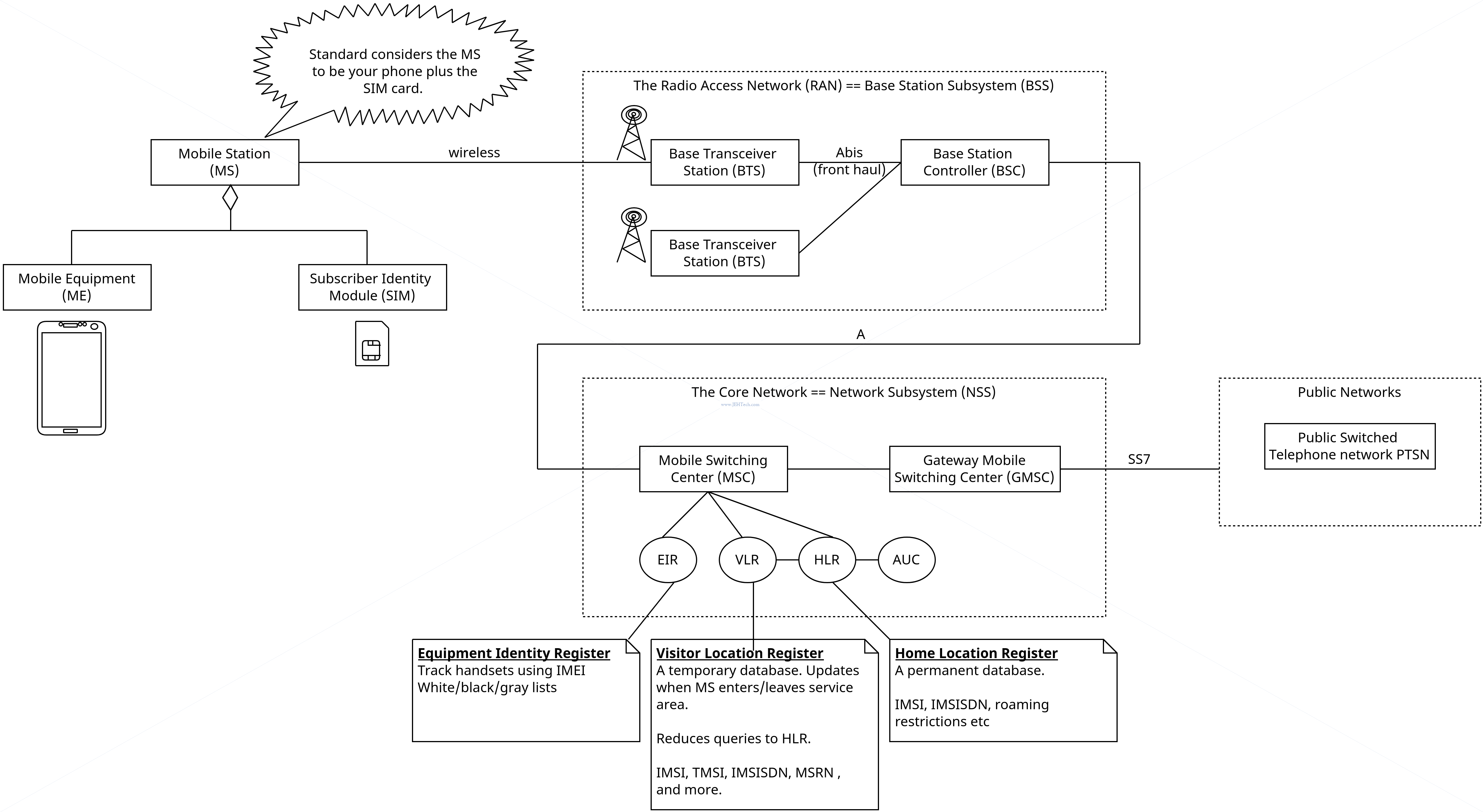
The GSM architecture consists of three major interconnected subsystems that interact with themselves and with users through certain network interface. The subsystems are Base Station Subsystem (BSS), Network Switching Subsystem (NSS) and Operational Support Subsystem (OSS). Mobile Station (MS) is also a subsystem but it is considered as a part of BSS.
Base Status Subsystem
The Base Station Subsystem (BSS) consists of the Base Transceiver Stations (BTS) and the Base Station Controller (BSC).
Many BSS connect to one BTS and many BTS connect to one MSC.
The BTS provides the radio link to your phone and communicates with the BSC, which manges the radio resources for the BTS, assigning frequencies and time slots. The BSC also handles call setup and handover. It also switches traffic to/from the MSC.
The phone (ME) will measure the signal strength from the BTS it is connected to. It will also measure the signal strength of neighboring BTS's and sends them to the BSC, which sends them to the MSC. This is used byt the BSC to control MS handover and control power between the BTS and MS.
Network Subsystem
The NSS is responsible for all the call switching and routing and tracking the location of the mobile.
The Mobile Switching Center (MSC) is a digital switch that performs call setup, routing between the MS & other MSCs or external networks.
A Mobile Switching Center (MSC) is a core part of the GSM/CDMA network system. It acts as a control center of a Network Switching Subsystem (NSS). The MSC connects calls between subscribers by switching the digital voice packets between network paths. It also provides information needed to support mobile service subscribers. [[Ref]](https://www.simbase.com/iot-glossary-dictionary/mobile-switching-center#:~:text=A%20Mobile%20Switching%20Center%20(MSC,voice%20packets%20between%20network%20paths)
It also handles inter BSS and inter MSC handovers. When a mobile moves between two BSCs the handover has to be handled by the MSC as this is the common parent. If a mobile moved between two BTS within one BSC coverage area then the BSC could handle the handover.
IMEI of all the mobile stations are stored in the database known as EIR (Equipment Identification Register). The network can check this list in order to confirm whether mobile has been stolen or not.
...
The TMSI identifier is assigned by VLR entity after GSM mobile station establishes communication with the GSM network(i.e. Base station or BTS). The network then uses TMSI instead of IMSI during call processing and call management tasks.
This identifier is shorter compare[d] to IMSI number. Hence it is more efficient to transmit. The purpose [is] to use TMSI inplace of IMSI is to provide security to the mobile subscriber, as IMSI need not have to be transmitted continuously.
Home Location Register (HLR)
- Central DB for subscriber/mobile uer info
- Subscriber ID
- Auth Key
- Subscriber registration status
- Services a mobile subscriber can use
- Current location of subscriber
The network keeps track of the last known location of the MS in the VLR and HLR.
Visitor Location Register (VLR)
- Temporary data - reduce burden on HLR as this is a central database.
Equipment Identity Register:
- White list - authorised IMEs allowed to use network
- Black list - list of IMEIs of mobiles that are barred
- Gray list - list of IMEIs of mobiles that are being traced
Channels
Two types:
- Traffic channels (TCHs)
- Control channels (MS registration, handover, etc etc)
- Broadcast
- Broadcast Control CHannel (BCCH) - Need FCCH and SCH to be able to device this channel.
- Frequency Correction CHannel (FCCH)
- Syncrhonization CHannel (SCH)
- Common
- Paging CHannel (PCH) - Downlink only. This is how the BTS informs the MS of incoming calls.
- Random Access CHannel (RACH)
- Access Grant CHannel (AGCH)
- Standalone Dedicated Control CHannel (SDCCH)
- Broadcast
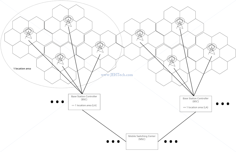
Location Areas
Each MSC area is subdivided into many local areas. Each such area has an identifier called the Local Area Identity (LAI).
The LAI is structured like so:
+-----+-----+-----------------------------+
| MCC | MNC |             LAC             | < LAC is "Location Area Code" - only unique to the MSC service area, by...
+-----+-----+-----------------------------+   ...prefixing it with the MCC and MNC it makes it unique globally so...
 ^^^^^ ^^^^^                                  ...roaming is possible .
 ^^^^^ 2/3 digits
 3 digits
Location areas do not all have to be the same size and contain different number of base stations per area.
When a mobile is in the IDLE state, i.e, not in a call, only the location area is known, not exactly which base station the mobile is connected to, so to page the mobile, the network has to page all the base stations to find the mobile.
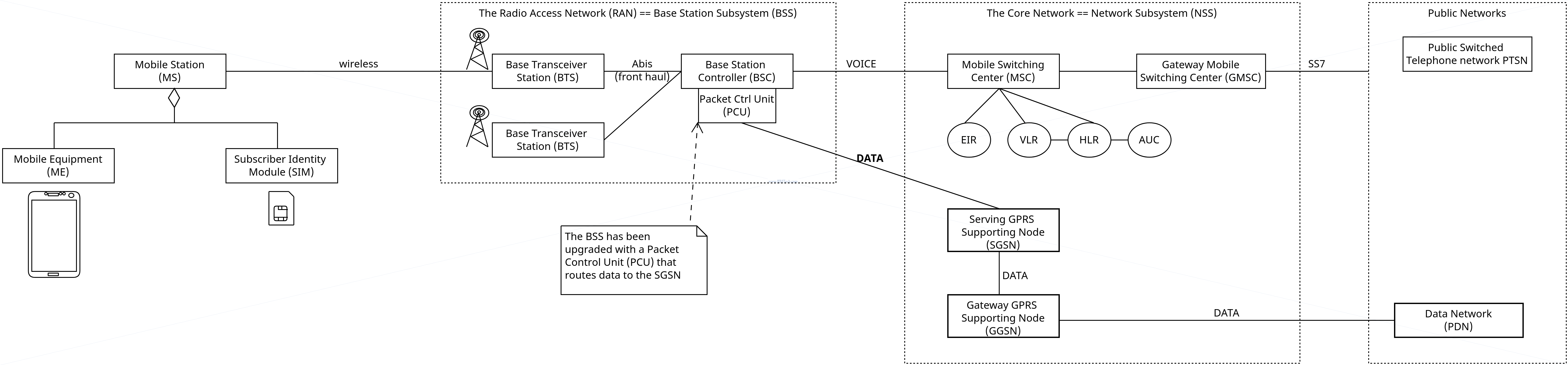
GPRS
GPRS introduces new network elements to allow packet data transmission. Remember GSM is analog and has no data transmission capabilities. GPRS introduces the ability to use data.
- Serving GPRS Support Node (SGSN) - authenticates GPRS mobiles & network registration. charging info.
Part of the GPRS infrastructure, the SGSN provides switching functionality, security and authentication via the HLR for GPRS users. The SGSN's primary interfaces are with the GGSN, HLR and PCU.
[Ref]. Coverage area of a MNO is divided into SGSN areas. - Gateway GPRS Support Node (GGSN) - interface and router to external networks. routes packets through IP backbone: think router. GGSN assigns the ME and IP address and acts as the anchor for that address: as the ME roams through the network and changes SGSN areas the GGSN keeps track of which SGSN the ME is in and provides the constant IP address and routes traffic to and from the correct SGSN.
The gateway GPRS support node (GGSN) converts the incoming data traffic coming from the mobile users through the Service gateway GPRS support node (SGSN) and forwards it to the relevant network, and vice versa. The GGSN and the SGSN together form the GPRS support nodes (GSN).
[Ref]
3G
The development of 3G was standardised by the 3rd Generation Partnership Project (3GPP) as formed in 1998. It was a group of telecom vendors and operators.
They introduced he 3G Universal Mobile Telecoms Service (UMTS) technology in 2001, aka Wideband CDMA (WCDMA). CDMA is Code Division Multiple Access.
Interestingly the 3G architecture kept the 2G GPRS/Edge core network! It only uses a different access network!
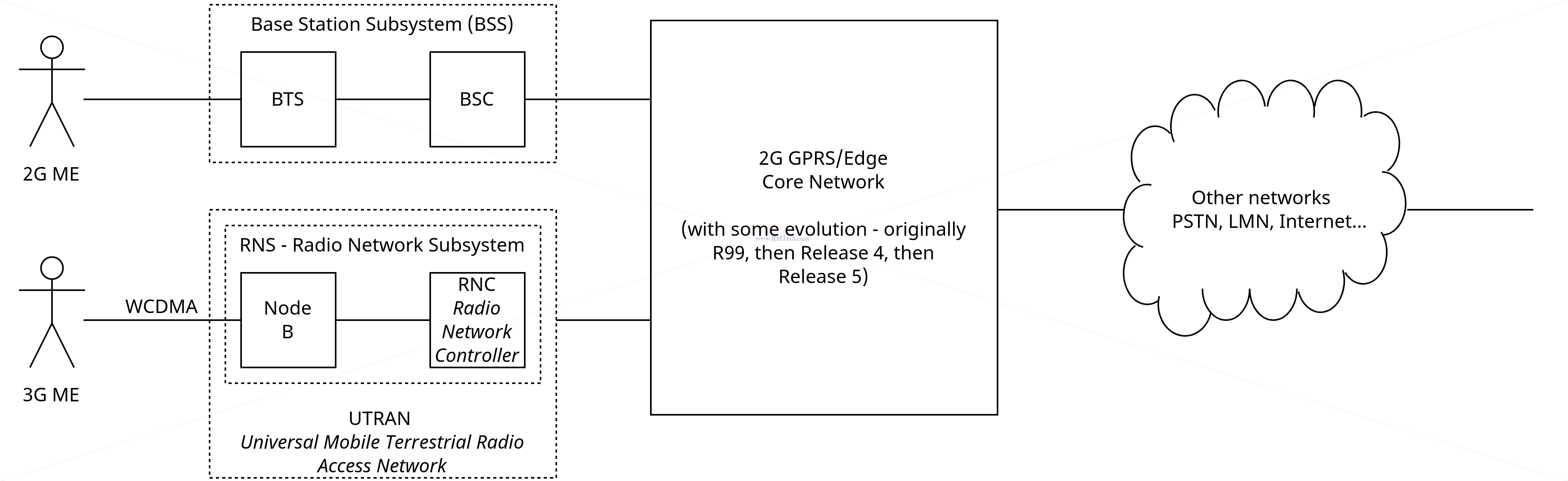
NodeB and RNC
Node B is responsible for the wireless comms using the speading/despreading of the signal using code division multiplexing and for error correction.
The power (signal strength) and Frame Error Rate (FER) is sent, be the ME, to node B and then to the Radio Network Controller (RNC)
The RNC:
- Switches traffic and signalling to/from the BSC and Core Network (CN).
- Manages the radio resources of the Node Bs that it controlles: handover and power control.
- Aggregates traffic from the NodeB's to the CN and vice versa including packet scheduling (QoS) and congestion (load) control (can trigger handovers to less loaded NodeB's)
- Does admission control and code allocation.
Core Network
There were three versions of the CN:
- Release 99: The GPRS CN?
- Release 4: The MSC is divided in two: it is split into the media gateway and the MSC server. The media gateway handles traffic and the MSC server handles signalling.
- Release 5: Adds IT Multimedia Subsystem (IMS) between the packet switched core and the IP network. Allows voice calls to be packet switched! Voice calls can now be routed over the circuit switched (CS) core or now the packet switched (PS) core.
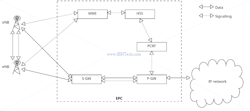
4G LTE
The access network is called the "Evolved Universal Terrestrial Radia Access Network" or "EUTRAN". Base stations called eNodeB's (eNB). Unlike 3G, there is no entity that acts as a Radio Network Controller (RNC): some of its functions have been pushed onto the eNB and other functions into the core network.
The core network is called the "Evolved Packet Core" or "EPC". Everying is IP. There is no Circuit Switched (CS) core... there is only a Packet Switched (PS) core. I.e., voice is over IP.
The access technology is Orthogonal Frequency Division Multiplexing (OFDM). In the uplink direction Single Carrier Frequency Division Multiple Access (SC-FDMA) is used (can be efficiently amplified using cheap amplifiers in the ME) and in the downling direction Orthogonal Frequency Division Multiple Access (OFDMA) is used (BSCs can use more expensive amplification tech). Both are variants of OFDMA.
The LTE network called EPS (Evolved Packet System) is an end-to-end (E2E) all IP network; EPS is divided into two parts - LTE part which deals with the technology related to a radio access network (E-UTRAN) and EPC part which deals with the technology related to a core network.
Voice calls made over an LTE network will either be done using VoLTE (Voice over LTE) which is a packet switched technology, or if required, can fallback to a CS network and use traditional voice calling.
Good old ChatGPT summarises it nicely (which I double checked to make sure it wasn't hallucinating lol)
LTE (Long-Term Evolution) is primarily designed for packet-switched (PS) services, which means it is optimized for data transmission. However, it does have the capability to support circuit-switched (CS) services, but this support is typically implemented using fallback mechanisms rather than native CS support. This is often referred to as "CS Fallback."
CS Fallback allows a device connected to an LTE network to use CS services when necessary. CS services are traditional voice and SMS services that are circuit-switched, whereas PS services include data services like internet browsing....
When a mobile device is attached to a 4G network and makes a phone call, the call is not necessarily VoIP (Voice over Internet Protocol) in the traditional sense. 4G networks primarily use packet-switched technology for voice calls, which is a different approach from traditional circuit-switched voice calls used in 2G and 3G networks.
Here's how it works:
- VoLTE (Voice over LTE): In many 4G networks, voice calls are carried using a technology called Voice over LTE or VoLTE. VoLTE allows voice data to be packetized and transmitted over the LTE network, similar to how data is transmitted for internet services. This means that the voice call is technically transmitted over an IP network, making it VoIP-like. However, VoLTE is specifically designed to prioritize voice traffic and maintain high-quality voice calls.
- CS Fallback: In some cases, if a device is not VoLTE-capable or if the network doesn't support VoLTE, a mobile device may fall back to a 2G or 3G network for voice calls. These older networks use traditional circuit-switched technology for voice calls.
So, whether a phone call on a 4G network is VoIP or not depends on whether VoLTE is supported and used in the network and on the device. In most modern 4G networks and devices, VoLTE is the preferred method for handling voice calls, making them VoIP-like in nature, but with a focus on maintaining voice call quality.
Some verbage for the IoT world:
- 4G LTE Cat-M1 is LTE-M, aka eMTC
- 4G LTE Cat-NB1/2 is NB-IoT, also known by "E-UTRAN NB-S1/2 mode"
LTE Cat-M1 is a Low-Power, Wide-Area Network (LP-WAN) designed specifically for purpose-built devices, like trackers or water meters, that transmit small to medium amounts of data over wide ranges. LTE Cat-M1 is a category of 4G long-term evolution (LTE) technology for machines (M). LTE-M is an abbreviated name for LTE Cat-M1. ... LTE Cat-M1 was created to replace 3G. Cat-M1 and other low-power devices strip out that legacy technology
LTE Cat-M1 and NB-IoT are complementary LPWAN networks but use different technologies.
-- [Ref]
NarrowBand Internet of Things (NB-IoT): NB-IoT is a non-backward compatible variant of E-UTRAN supporting a reduced set of functionality See ETSI TS 123 122 V14.2.0)
LTE-M is perfect for medium-throughput applications requiring low power, low latency, and/or mobility, like asset tracking, wearables, medical, POS and home security applications. ... NB-IoT is perfect for static, low throughput applications requiring low power and long-range, like smart metering, smart agriculture and smart city applications. It also provides better penetration in, for example, cellars and parking garages compared to LTE-M.
-- [Ref]
Mobile Management Entity (MME)
- Similar to VLR in 2G/3G
- Manages UE registration, authentication
- Stores UE temporary data/context
- Performs bearer management and establishment
Home Subscriber Service (HSS)
- Central DB for all subscriber information
- Stores security keys for authentication
- Stores user/subscriber info such as ID, roaming restrictuions, QoS etc.
Serving Gateway (S-GW)
- Handles user data connectivity between the UE and EPC
- Simply a router - packet routing and forwarding between eNB and P-GW
- QoS
- Data path anchor for handover between eNBs and inter 3GPP networks (2G/3G)
- Idle mode downlink packet buffering
PDN Gateway (P-GW)
- Allocates IP addresses to UE during bearer establishment.
- Deep packet inspection for unorthorised or malicious packets
- QoS
Policy and Charging Rules Function (PCRF)
- TODO
5G
- Usage scenarios - wide variation of services and their associated requirements:
- Support for Enhanced Mobile Broadband (eMMB) for UHD streaming etc: high data rate, high area traffic capcity etc.
- Support for Massive Machine Type Communications (mMTC): sensors etc: high connection density and low power requirements.
- Support for Ulta-Reliable and Low Latency Communications (uRRLC): e.g. industrial automation, remote control.
- Uses OFDMA with scalable sub-carrier spacing.
- Uses Massive Multiple Input Output (MIMO) technology in which a large number of antennas work together to improve both coverage and data rate. Sometimes known as "beamforming" technology.
- MIMO uses large antenna array on base station.
- Number of antenna array lements is meant to be much larger than the number of UEs.
- Narrower beams can be directed at different UEs, which improves the SNR.
The quality of service is the percieved bit rate by the user, i.e. the nubber of correct, uncorrupted, bits received per second. 4G is meant to be able to run at 10 Mbits/s download rate. This is too slow for HD movies, which is one reason why 5G is now around: better QoS.
Reliability is the probability of successfullyu receiving a block of data.
Another reason is latency. Imagin remote controlling a robot. 4G gives latencies >= 10ms. Too slow for remote control. Another reason for 5G.
Connection density is the total number of devices per unit area. 4G can handle around 100,000 objects per km^2. 5G aims to handle ~1 million.
The original 8 5G KPIs [Ref]:
- Peak data rate. This is when network is not overloaded and conditions are favourable. Minimum Downlink: 20 Gbps, Uplink 10 Gbps.
- User experienced data rate. Minimum Downlink: 100 Mbps, Uplink: 50 Mbps
- Spectrum efficiency. Minimum Downlink: 30 bits/sec/Hz, Uplink: 15 bits/sec/Hz
- Mobilty. Dense Urban: up to 30 Km/h, Rural: up to 500 Km/h
- Connection density. 1 x 10^6 devices/Km^2
- Network energy efficiency.
- Area traffic capacity. Downlink: 10 Mbits/sec/m^2 in indoor hotspot
And also.
- Reliability.
5G cannot fulfill all these goals simulataneously.... no mobile comms system can. Thus, 5G defines multiple different configurations to favour various combinations of the KPIs:
- enhanced Mobile Broadband (eMBB): very high mobile throughput.
- massive Machine Type Communication (mMTC): focus is on connection density and energy efficiency. this was possible, somewhat in 4G using NB-IoT and LTE-M.
- ultra Reliable Low Latency Communication (uRLLC): focus on very low latency and high mobility.
5G introduces the SUPI - Subscription permanent Identifier, which can be the IMSI, but is more generic in concept because it can be entworkk-specific for private networks: the format is flexible.
5G Network Types
5G introduces a new radio interface called NR, for New Radio, which is mainly an evolution of LTE with a higher throughput and lower latency.
Non Standalone Architecture
In the non-standlone architecture the 5G RAT still ends up "plugged into" the 4G core network. The 4G eNB (e-Node B) is supplimented with an en-gNB base station addition. A 4G connection between the UE and the network in maintained.
Standalone Architecture
In the standalone architecture it is 100% 5G both for the RAT (the basestation is a gNB (g-Node B)) and the core network (5GC).
Sidelink Communication
P2P connection of "things", like cars, for example.
Security
- Interconnected networks - cannot trust devices from other MNO networks.
-
Bidding-down or downgrade attacks - when a UE is made to work in a downgraded way. For example, forcing a 4G capable UE to connect to a 2G network where there is no authentication technology.
The goal of such an attack, no matter what type of attack is applied or what attack vector (a characteristic of the network that can be exploited by the adversary) is used, is to weaken the security. Enforcing a weaker connection opens the door for follow-up attacks in which the adversary can, for example, try to eavesdrop on the connection. Never let Me Adown Again: Bidding-Down Attachs and Mitigations in 5G and 4G (blog)
Bidding-down attacks reduce the security of a mobile network connection. Weaker encryption algorithms or even downgrades to prior network generations an adversary to exploit numerous attack vectors and harm the users of a network. Never let Me Adown Again: Bidding-Down Attachs and Mitigations in 5G and 4G (preprint paper).
Power Saving
There are two solutions that optimize device power consumption: PSM and eDRX.
PSM
- See POWER SAVINGS FOR CELLULAR IOT DEVICES by Yong Shi January 31, 2022
- Mobile does not monitor paging (broadcasts sent to all cells in a location area/routing area/tracking area) and becomes unreachable for Mobile Terminated (MT) services, which are services where the mobile is contacted via the network. For example an SMS is terminated at the mobile which receives it.
- This goes beyond Idle Mode behavior because in this mode power hungy tasks like neighbour cell measurements and listening to the paging channel (maintinging reachability) are still performed.
- Device stays registered in network and maintains connection configuration. This means that when leaving PSM the device does not need to re-attach to network and setup the connection, which is a power consuming activity.
- PSM is left only when the device needs to do things like periodic Tracking Area Updates (TAUs) / Routing Area Updates (RAUs). In general these are refered to as Mobile Originated (MO) services.
- An Active Timer is used after comms: device remains reachable (monitors paging channel) until the timer expires, at which point device goes low power, and is unreachable, until the next event which causes it to leave this state.
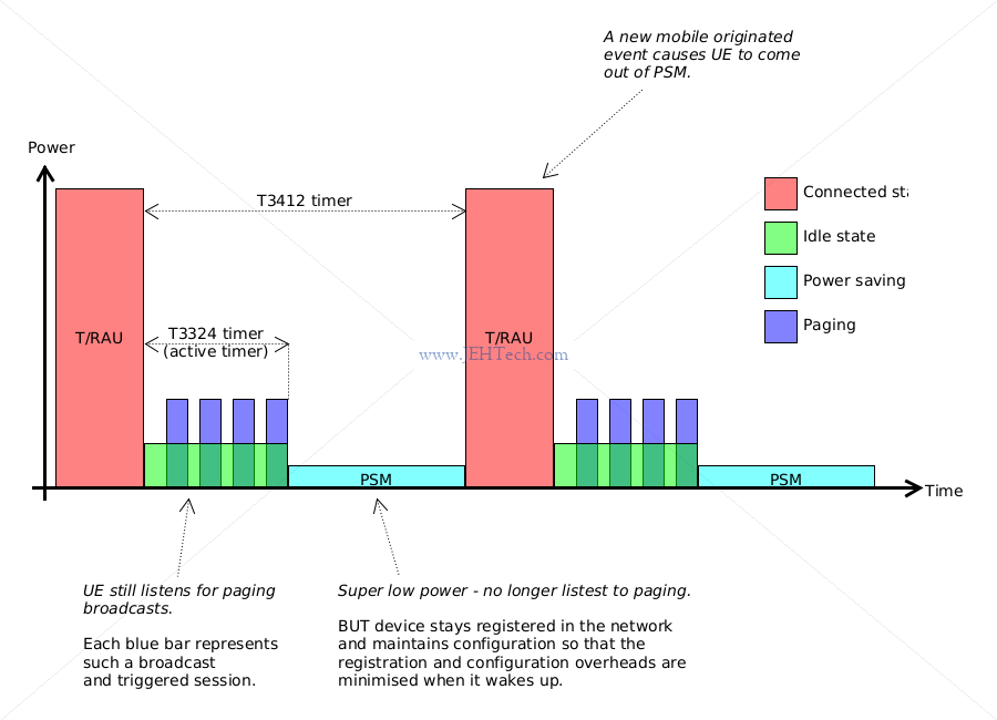
All timers are negotiated on network connect. The T3142 timer can be very long which allows devices that infrequently send data (think IoT meters etc), to stay in lower power mode for months at a time, if not longer.
IoT devices typically send or receive data intermittently. Between periods of data transmission and reception, a device can sleep to minimize power consumption and maximize battery charge. The energy cost of completely detaching from the network at sleep, then re-attaching upon wake is high, so LTE allows the device to maintain its network attachment during sleep. However, the host network will periodically page the device, which needs to wake and respond. The device will then sleep again until it receives the next page or has to wake to send data.
This wake-respond-sleep process consumes only a small amount of energy, but its cumulative energy consumption can become significant over the lifetime of a device. Power Save Mode addresses this by letting IoT devices agree to an extended sleep period with the network. During this time, the network doesn't page the device, which can then wake only when it needs to send data or when the sleep period expires.
...
In an active PSM period, the modem's radio is fully shut down and the device cannot send data or be reached. During development, you should be aware that the device's AT channel may also be closed down.
Data intended for the sleeping device is buffered: 3GPP requirements mandate that data packets must be stored by the network.
They had en even better explanation in another of their blogs:
Power Saving Mode (PSM) - The PSM feature allows an IoT device to sleep for extended periods of time without being woken up by network paging. Typical cellular devices actively transition between two modes – IDLE and ACTIVE. When the device is not sending/receiving traffic it goes IDLE, which has a positive effect on battery life. If there are IP packets that need to be delivered to the device, the network pages for the device. The device must respond to the page and transition to ACTIVE mode to receive the traffic. This has an impact on IoT devices that are power-constrained. PSM allows these IoT devices to negotiate an extended sleep period (hours or days) with the network and avoid being paged during that sleep cycle. If there is any traffic that arrives for the device during the sleep period, the traffic is buffered in the network (at least the last 100 bytes) and delivered when the device becomes ACTIVE.
eDRX
- Extends the DRX cycles to allow a device to remain in a lower power state for longer between paging occasions. This has the advantage, v.s. PSM, that the device is periodically available for longer for MT terminated services without requiring an MO trigger.
Twilio has the following to say about the difference between PSM and eDRX:
While not providing the same levels of power reduction as PSM, eDRX can offer a good compromise between device reachability and power consumption. eDRX can be used alongside PSM to obtain additional power savings, or it can be used on its own.
PSM is more power efficient because PSM cycles are much longer than eDRX cycles. As a result, the device can enter into a deeper, lower power sleep state with PSM than it can with eDRX.
Their blog also gives a nice little bit of extra detail:
PSM and eDRX are complementary and can both be used by a Cat M device. eDRX helps the device sleep a bit longer, wake up at fixed intervals, and generally reduce "chattiness" between the device and the network. PSM helps the device sleep for much longer - hours or days.
Talking With A Modem: AT Commands
The Twilio Cellular Modem Knowledge Base is a really good resource.
These are just quick notes on some commands for quick reference. Not trying to duplicate the manual here so for details look at modem manual.
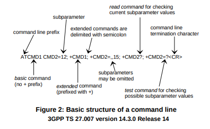
AT commands come in at least two forms: 1. Basic AT commands 2. Extended AT commands
Basic AT commands have the following format:
ATCMDb=123
||||||^
||^^^^Commands can have parameters
^^ The basic command is "CMDb" (substitute an actual command here).
All AT commands are prefexed with the charaters "AT". No space between "AT" and "CMDx"
because this is a basic command
The ETSI standard has a good figure in it, replicated below....
As a colleague of mine warned me about: When parameters are omitted the default value is used. You need to check what the default value is defined as. If the default value is an empty string, then ,, and ,"", are logically equivalent. If the default value is "chicken" for example, then ,, would keep the default value of "chicken", whereas ,"", would not!
For a concrete example, consider AT+CGDCONT...
You have to pay attention to the device manuals notes:
<PDP_addr> Number See <PDP_addr>. The default value is "0.0.0.0"
So if you want the default IP address assignment, you either need to use ,, or ,"0.0.0.0". Using ,"", could well fail with an error, or at the very least be reliant upon undefined behaviour.
For example, some basic AT commands include:
ATI  // Display Product Identification Information
ATI0 // Request type number of device
ATI6 // Request mobile boot sequence version
ATI9 // Request modem and application version
AT&V // Display current configuration
Each command will be a two or more line replace with:
COMMAND-ECHOED
....
OK or ERROR
Note ERROR is not very informative which is why extended error reporting (CME errors) are usually enabled (AT+CMEE=1)
So, on a Ublox R4, for example:
>> ATI
Manufacturer: u-blox
Model: SARA-R412M-02B
Revision: M0.10.00 [Mar 28 2019 17:13:41]
SVN: 05
IMEI: 354679092470650

OK

>> ATI0
SARA-R412M-02B

OK
An error without CME errors enabled would look like this (no SIM inserted in this example):
>> AT+CIMI

ERROR
Enabling numeric CME errors:
>> AT+CMEE=1

OK
>> AT+CIMI

+CME ERROR: 13
Enabling human readable CME errors:
>> AT+CMEE=2

OK
>> AT+CIMI

+CME ERROR: SIM failure
Extended commands are prefixed with a "+":
AT+<COMMAND><SUFFIX><DATA>
As for the AT commands themselves, a generic example could be the following:
AT+CMDe=,,15
Extended commands come in 3 flavours:
- Set: Suffix is "=". Think set a property. Property might enable/disable something, cause a specific behavior etc.
- Read: Suffix is "?".
- Execute: No suffix. Makes modem do something, think verb.
- Test: Suffix is "=?". Asks about capabilities and if command understood/supported.
However, not all AT commands follow this convention religiously. For example, AT+CIMI has the same functionality as AT+CIMI?: the CIMI can be read without using a "?" suffix, so it looks like an execution command, but really is doing a read of sorts.
Standard commands will be something like "AT+C....". Vendor specific commands usually replace the C with something. For example UBlox specific AT commands look like "AT+U..." and Spredtrum devices like the SM5100B look like "AT_S..." etc etc.
A more concrete example on the UBlox R4, requesting the IMEI:
>> AT+CGSN
354679092470650

OK
Standard
Information About Base Station / Cell
| Command | MCC | MNC | RAT | LAC | CI | RAC | dBm | Qual | BSIC | ARFCN | ULF | DLF | SC |
|---|---|---|---|---|---|---|---|---|---|---|---|---|---|
| AT+COPS? | Y | Y | Y | ||||||||||
| AT+CGREG=2 | Y | Y | Y | Y | |||||||||
| AT+CGED=4,1 | Y | Y | Y | Y | Y | Y | Y | Y | Y | Y | |||
| AT+DCSQ | Y | Y |
Where:
- BSIC = Base Station Identity Code
- ARFCN = Absolute Radio Frequency Channel Number
- ULF = Uplink Frequency
- DLF = Downlink Frequency
- SC = Scrambling Code.
Identifying Information About Modem, SIM, etc
| Command | Description |
|
Display Product Identification Information. E.g: >>>ATI Manufacturer: u-blox Model: SARA-R412M-02B Revision: M0.10.00 [Mar 28 17:13:41] SVN: 05 IMEI: 354679092470650 OK |
|
Module information: Module type number request. E.g: >>>ATI0 SARA-R412M-02B OK |
|
Firmware information: Modem and application version request. E.g: >>>ATI9 M0.10.00,A.02.14 OK |
|
Request manufacturer identification E.g: >>>AT+GMI u-blox OK |
|
Request model identification E.g: >>>AT+GMM SARA-R412M-02B OK |
|
Request the IMSI (International Mobile Subscriber Identity). E.g: >>>AT+CIMI 234500002006009 OK |
|
Request the IMEI (International Mobile station Equipment Identity). E.g: >>>AT+CGSN 354679092470650 OK |
|
Returns the ICCID (Integrated Circuit Card ID) of the SIM-card. ICCID is a serial number identifying the SIM. E.g: >>>AT+CCID +CCID: 8944502006180060098 OK |
|
Restricted SIM access: Allows easy access to the SIM database by sending SIM commands as defined in [ETSI TS 102221](https://www.etsi.org/deliver/etsi_ts/102200_102299/102221/15.00.00_60/ts_102221v150000p.pdf) For example, the command `AT+CRSM=176,28486,0,0,17` is a read binary command (176), reading elementary file (EF) identified by ID `28486 (0x6F46)` (EFs described in [3GPP TS 31.102](https://portal.3gpp.org/desktopmodules/Specifications/SpecificationDetails.aspx?specificationId=1803)). From the spec, on can see that `6F4F` is the service provider name (EFSPM). Both P1 and P2 are zero indicating no offset is applied. AT+CRSM=176,28486,0,0,17 +CRSM: 144,0,"0053747265616DFFFFFFFFFFFFFFFFFFFF" OK |
Network Registration
Registration takes place when a cellular module successfully connects to a cellular network via a cell tower. Until a modem is registered, it will not be able to establish a data session — a process called attachment — or even exchange SMS traffic. A modem can make multiple registrations depending on which radio access technologies (RATs) it supports and which are made available by the cell tower ... [but] Only a single registration is required to commence normal operations.
All the registration commands have the same response: +<CMD>=<urc_mode>,<registration_state>[,<additional_information>], where <registration_state> tells
you whether the modem has registered with a network using that Radio Access Technology (RAT). States 1, connected to home network, and 5, connected and roaming,
are what you're looking for!
| Command | Description |
|
Signal quality. Returns the radio signal quality information. |
|
Signal quality. Returns the *extended* radio signal quality information. |
|
Attach or detach the device to packet domain service. |
|
GSM network (cirtcuit switched) registration status/report. The set command configures whether URCs are emitted by the modem. E.g., the set command The read command reports the current mode and network registration status. |
|
GPRS network (packet switched) registration status/report. Very similar to `AT+CREG` but for GRPS networks |
|
LTE/EPS network (packet switched) registration status/report |
|
The `+COPS` command selects a Public Land Mobile Network (PLMN) automatically or manually, and reads and searches the current mobile network. |
|
Periodic serving cell reports are enabled by an `AT+CGED=4,1`` command. |
|
Preferred operator list. |
|
Preferred PLMN list selection. |
|
UBlox specific Radio Access Technology selection. Can be used to set the allowable RATs to be used when connecting to networks. If you get the CME Error "operation not supported" then you need to update the |
Easiest thing is to enable URCs for the registration to determine registration state. It is possible to poll using the query commands, but this is less efficient.
Circuit Switched (CS) v.s. Packet Switched (PS)
It is possible to be registered with any network and be both CS and PS attached or just either CS or PS attached.
For example, when connected to a GSM network one can only be CS attached. On a GPRS network however, one cab be CS and PS attached, i.e. have phone/sms and internet, or, for example just PS attached, i.e., have only internet access. One could also be on a GPRS network and only be CS attached.
Generally a modem will do "combined registration" when connecting to a network, which means that it simultaneously performes registration for CS and PS functions.
In LTE (4G) and 5G networks everything is packet switched so phone calls will be VoIP. However, LTE also has a CS fallback mechanism so can be both CS and PS attached.
Whether there is a concept of CS being somehow "virtual" on pute 4/5G networks when only the 4/5G access technology and core networks are used I'm not sure about. Whether such a concept as CS attached makes sense in this scenario I don't know, i.e., LTE can make voice calls useing VoLTE, which is packet switched, but could the service still be somehow considered as a "virtual" CS service? Dunno!
See the AT commands AT+CGATT and on Ublox devices AT+USVCDOMAIN.
An Example Network Registration Sequence
Some worked example sequences:
A. Deregister from the current network:
>  AT+COPS=2

OK
B. Find out what networks are available (the command takes some time to return anything)
>  AT+COPS=?

+COPS: (1,"234 10","234 10","23410",0),(1,"234 30","234 30","23430",0),(1,"234 15","234 15","23415",0),,(0,1,2,3,4),(0,1,2)

OK
The reply means the following:
+COPS: (1,"234 10","234 10","23410",0),(1,"234 30","234 30","23430",0),(1,"234 15","234 15","23415",0),,(0,1,2,3,4),(0,1,2)
        | |        |        |       |                                                                    |           |
        | |        |        |       AcT                                                                  |            Supported formats
        | |        |        numeric oper mmc/mnc                                                         Supported modes
        | |        short oper
        | long oper
        stat
So we have the following network operators in the format MMC, MNC, name:
- 234 15 Vodafone UK, GSM
- 234 10 O2 UK, GSM
- 234 30 T-Mobile UK, GSM
C. Lets try to get the device to automatically register on the network.
>  AT+COPS=0 # Auto register with network

OK
No URCs have been enabled at this stage so the only way to find out if a registration has
succeeded is to poll using the AT+COPS? query:
>  AT+COPS?

+COPS: 0,0,"234 15 Stream",3

OK
The reply to the AT command has the format +COPS: <mode>[,<format>,<oper>[,<AcT>]] which means
that the modem state is:
- mode = 0 -> automatic registration
- format = 0 -> long alphanumeric
- oper = "234 15 Stream" -> Vodafone UK
- act = 3 -> GSM/GPRS with EDGE availability
So, we know that we are registered on the Vodaphone Uk network using 3G.
D. Change the reporting format to numeric:
>  AT+COPS=3,2 # Set format to numeric

OK

>  AT+COPS? # Get current status again, now look how the format is different

+COPS: 0,2,"23415",3

OK
E. Now, rather than using automatic registration, lets force the modem to connect to a specific MNO:
>  AT+COPS=2 #Deregister from network

OK

>  AT+COPS=1,2,"23410" # Connect to specific provider, in this case O2 UK

OK

>  AT+COPS?

+COPS: 1,2,"23410",3

OK
F. Now let's enable URCs (Unsolicited Result Codes). These are messages sent by the modem that are not triggered as a response to an AT command.
> AT+COPS=2 # Deregister from network

OK

> AT+CEREG=4 # Enable LTE/EPS network registration URCs

OK

> AT+CGREG=4 # Enable GPRS network registration URCs

OK

> AT+COPS=1,2,"23410" # Try to connect to O2 network

OK                  # AT command completes

+CGREG: 5 #<<<< THIS IS A URC!!! Says its registered and roaming
Radio Access Technology
One thing you might have noticed when we used the AT+COPS=? command to see what networks were
available was that they were all GSM networks. Really? Not newer technologies visible?
Turns out, of course there are. I need to configure the allowed RATs...
# Set the RAT order of preference to be LTE, NB-IoT, GPRS/eGPRS
> AT+URAT=7,8,9

OK

# Now lets see what networks are available....
> AT+COPS=?

0),(0,"234 10","234 10","23410",0),(0,"234 30","234 30","23430",0),(0,"234 15","234 15","23415",7),(0,"234 15","234 15","23415",9),(0,"234 30","234 30","23430",9),(0,"234 10","234 10","23410",9),,(0,1,2,3,4),(0,1,2)

OK
Ah! Quote the list now! Each of the previously visible MNOs now has an additional E-UTRAN (4G/LTE) network. In the examples that follow only the GSM RAT was enabled, but could have resily enabled LTE too...
NOTE: You must reset the device for the URAT changes to become effective. Use AT+CFUN=15 (or =16 to include a SIM reset, which you dont need in this case though).
MNO Profiles
This is a Ublox concept, I think.
MNO profiles provide a powerful and flexible method to configure the SARA-R4 series module to seamlessly work with the SIM of the selected network operator.
Using the MNO profiles the module is dynamically configured to use the proper bands, RATs, and the operator-dependent protocol stack settings needed to operate on the home network in full compliance with the mobile operator requirements.
This might be, in part, why the above registration example was "simple". On the device if I query the MNO profile in use I get the following:
AT+UMNOPROF?

+UMNOPROF: 100

OK
This means that the currently configured profile is Europe.
From the R4 manual one can see that the MNO profile sets:
- The band mask
- The RAT
- PDP context type
- Service domain
- LwM2M features (Lightwieght machine to machine protocol - for low power devices)
- Radio Manager Policy settings
- CIoT optimization configuration
- CIoT capabilities configuration
- MAC QoS inactivity timer(s)
- MTU size
Thus, I didn't have to configure any of the above myself.
One thing to note is that, if for example you want to modify the RATs being used (see +URAT) you
must set the MNO profile first, then the RAT, otherwise the profile will overwrite any RAT setting
made previously!
Modem Power Settings
| Command | Description |
|
Power Saving Mode (PSM) settings. See PSM |
|
Use extended discontinuous reception (eDRX) parameters. EDRX is an extension of the DRX feature that is used by IoT devices to reduce power consumption. |
Internet Access (IP)
| Command | Description |
AT+CGPADDR |
Get the IPv4 address assigned to the device. |
AT+CGCONTRDP |
Get the network assigned IP address and DNS server IP addresses. |
|
Defines a PDP context. Packet Data Protocol (PDP) context definition: Packet Data Protocol (PDP) context is a data structure that allows the device to transmit data using Internet Protocol. Eg APN name, IP address etc. It gives all the information required to allow an interconnection, via a fixed point in the core network, for the UE to connect to the data network, regardless of if the UE moves between cells, basestations etc. For example, the available PDP contexts can be queried like so: > AT+CGDCONT? +CGDCONT: 1,"IP","xxxx","0.0.0.0",0,0,0,0 # | | | | # | | | | # | | | PDP address # | | APN name # | PDP type # cid - used to identify the definition OK The above was already stored on my device, i.e., it had previously been configured (for a Twillio super SIM). If I needed other PDP context definitions I could use the set command to store more, for example Some APNs have usernames and passwords but these are essentially useless as they are well-known. Presumably when the system was designed it was envisaged providers might have different usernames and passwords for different SIMs etc, but that never happended! |
|
Activate or deactivate the PDP context. |
APN Access and Authentication
We saw above that the APNs have well known usernames and passwords, if they are even required. It is essentially useless - the username and password provides absolutely no authentication whatsoever.
But, if you get the username and password wrong, connection to the APN will fail!
APN connection will also involve some kind of authentication protocol - either PAP (Password Authentication Protocol) or CHAP (Challenge Handshare Authentication Protocol). Again this is pretty pointless because the username and passwords are already well known! But, get this wrong, and the APN connection will most likely fail!
The MNO may use a RADIUS server to do this authentication...
RADIUS (Remote Authentication Dial-In User Service) is a client-server protocol and software that enables remote access servers to communicate with a central server to authenticate dial-in users and authorize their access to the requested system or service.
...
RADIUS authenticates using two approaches:
Password Authentication Protocol (PAP). The RADIUS client forwards the remote user's user ID and password to the RADIUS authentication server. If the credentials are correct, the server authenticates the user and the RADIUS client enables the remote user to connect to the network.
Challenge Handshake Authentication Protocol (CHAP). Also known as a three-way handshake, CHAP authentication relies on the client and server using an encrypted shared secret. Compared to PAP, CHAP authentication is considered more secure because it encrypts authentication exchanges and it can be configured to do repeated mid-session authentications.
Some modems will do automatic selection of the authentication type. The Ublox R4 does, for example. So, normally setting the authentication type for your APN
doesn't need to be done. If there are problems however, setting a specific authentication type up, rather than doing auto detection, may help.
For Ublox see the AT+UAUTHREQ command.
An Example Of Package Data Bearer Activation
Once the modem has registered with a network it can activate a packet data bearer. Remember, a "bearer" just refers to the underlying network technology that carries the data traffic between the mobile device and the network infrastructure.
A. Use the AT+CGDCONT? to see what PDP context definitions are stored by the modem.
> AT+CGDCONT?

+CGDCONT: 1,"IP","super","0.0.0.0",0,0,0,0

OK
The above is an IP context for Twillio (we know this because "super" is their APN name).
I have an O2 (UK) M2M SIM inserted so first I need to find out O2's APN name, which is not publicly available, and is "xxxx" (redacted).
I therefore need to...
B. Create a new PDP context definition for O2:
> AT+CGDCONT=2,"IP","xxxx"

OK
C. Re-list the available PDP context definitions to check this really worked:
> AT+CGDCONT?

+CGDCONT: 1,"IP","super","0.0.0.0",0,0,0,0
+CGDCONT: 2,"IP","xxxx","0.0.0.0",0,0,0,0

OK
It did, so now...
D. Use the AT+CGACT? command to query the PDP contexts stats (active or inactive). The command should respond with +CGACT: <cid>,<status>, where <cid> is just a number that uniquely identifies a bearer and <status> is either 0 for deactivated or 1 for activated.
> AT+CGACT?

+CGACT: 1,0
+CGACT: 2,0

OK
In the above example, there is are 2 inactive PDP contexts with cids of 1 and 2.
E. Let's enable the PDP context we just created...
> AT+CGACT=1,2

+CME ERROR: requested service option not subscribed
Oops! What happened here? I made a mistake. Although the SIM connected to the O2 network, it is not an O2 SIM. What is happening behind the scenes is that there is a RADIUS query being sent to O2's RADIUS server. As the SIM is not an O2 SIM, the server denies the request.
It is an ARM Pellion SIM so I need to modify the PDP context to use the correct APN name!
F. Correct the APN name:
> AT+CGDCONT=2,"IP","arm-pellion-stream-apn-name-goes-here"

OK
G. Retry activating the context...
> AT+CGACT=1,2

OK
Yay!
H. Use the AT+CGCONTRDP=<cid> command to query the dynamic parameters for the PDP context e.g. the IPv4 address assigned to the device and the IPv4 addresses for the primary and secondary DNS servers.
> AT+CGCONTRDP=2

+CGCONTRDP: 2,5,--ip redacted--,--ip redacted--,,--ip redacted--,--ip redacted--

OK
The above command returned us the following information:
- CID - 2
- Bearer ID - 5
- Local IP address (and possibly netmask), i.e. the IP address and subnet mask of the phone
- Gatway address
- DNS server primary address - not given
- DNS server secondary address
- P-CSCF (Proxy Call Session Control Function) server primary address
Internet Access (TCP/IP)
Opening sockets looks to be a vendor specific thing as I guess a modem doesn't have to support this as the modem client could implement the TCP/IP stack on top of the IP connection provided.
However, some devices add in this functionality for you. Ublox does as well as other vendors. I'll concentrate on Ublox here because that's what I'm learning with...
First thing is to set some of the security parameters
AT+USECPRF command to reset the security profile to defaults:
Use the AT+USECPRF command to configure the certificate validation to be level 3 i.e root certificate validation with check of certificate validity date
AT+USECPRF command to configure the minimum SSL/TLS version to be TLSv1.2
Use the AT+USECPRF command to configure the cipher suites to use cipher suite (0x003D) TLS_RSA_WITH_AES_256_CBC_SHA256
AT+CCLK={time}
The EVK-R4 user guide gives a good example of opening a socket, which I have just plugged into my terminal session with the board...
See also Test servier for cellular data modules, Ublox.
> AT+COPS?

+COPS: 0,0,"234 10 Stream",3

OK

> AT+USOCR=6

+CME ERROR: No connection to phone
Ooh, what happended here? I had rebooted the EVK and not re started the PDP context. Once the PDP context was reactivated it, well... you'll see...
# Activate the PDP context
> AT+CGACT=1,2

OK

# Create the TCP socket -- AT+USOCR=<protocol>[,<local_port>[,<preferred_protocol_type>[,<cid>]]]
# Where
#   protocol:  6: TCP
#             17: UDP
#
> AT+USOCR=6

# The response is +USOCR: <socket>, so the socket numnber/ID we've been assigned is 0
+USOCR: 0

OK

# Connect to the server -- AT+USOCO=<socket>,<remote_addr>,<remote_port>[,<async_connect>]
# The echo server details are provided by Ublox in their "Test server for cellular data modules" application note.
> AT+USOCO=0,"echo.u-blox.com",7

+CME ERROR: Operation not allowed
Oops! Something has gone wrong.
There are two PDP contexts available but only one is active, so one might hope that the R4 would known to associated the socket with the PDP context.
So how does it associated PDP contexts with sockets?. The answer is via the PDP context CID. Looking at the manual a little more closely one can see that the command syntax in full is...
AT+USOCR=<protocol>[,<local_port>[,<preferred_protocol_type>[,<cid>]]]
#                                                             ^^^^^
#                                                             Aha! Associate socket with PDP context
In the above <cid> specifies the PDP context that will be used for the socket operations
.
So try the following:
# Close the socket
> AT+USOCL=0

OK

# Re-open the socket and associate with PDP context 2
> AT+USOCR=6,,0,0,2

+CME ERROR: Operation not allowed
That didn't work either... reading a little further down the manual:
SARA-R4 / SARA-N4
- The `<local_port>` parameter is not supported; a random local port will be used while sending data.
- The `<preferred_protocol_type>` parameter is not supported.
- The `<cid>` parameter is not supported.
Oh great! So, it would appear that we can only use the first PDP context "slot"...
Delete all the PDP contexts defined on the board:
> AT+CGDCONT=1

OK

> AT+CGDCONT=2

OK

> AT+CGDCONT?

OK
Now that all the context definitions have been delated add a new context so that from the examples above, what was PDP context #2 effectively becomes context #1...
> AT+CGDCONT=1,"IP","arm-pellion-stream-apn-name-goes-here"

OK

> AT+CGDCONT?

+CGDCONT: 1,"IP","--redacted--","0.0.0.0",0,0,0,0

OK
OK, now try to create the socket...
> AT+USOCR=6

+CME ERROR: No connection to phone
Ah, for got to activate the context!!
# Activate the context
> AT+CGACT=1,1

OK

# Then create the socket
> AT+USOCR=6

+USOCR: 0

OK
Hooray. Lets continue with UBlox's example and connect to their echo server...
> AT+USOCO=0,"echo.u-blox.com",7

OK

# Receive a URC from the modem indicating that receive data is available (28 bytes)
+UUSORD: 0,28


# Retrieve the message
> AT+USORD=0,28

+USORD: 0,28,"u-blox TCP/UDP test service
                                         "

OK

# Close the socket
AT+USOCL=0

OK
U-Blox
For the UBlox devices it seems that, each command must be sent at least 20ms after the "OK" from the previous command!!!
| Command | Description |
AT+USVCDOMAIN |
Configures the service domain (CS/PS) upon network attach. Use to set whether upon network attach just one of the CS or PS domains are attached to or whether both are simultaneously attached to. |
AT+UPSV=x |
Power saving mode. x = 0 -> power saving disabled. |
AT+UANTR |
Antenna detection: measure DC component of load of cellular antenna. |
AT+UAUTHREQ |
|
AT+USIMSTAT |
Configure the SIM state reporting so that the unsolicited result code (URC) reports the (U)SIM toolkit REFRESH proactive command execution result |
AT+UMNOPROF |
Set Mobile Network Operator (MNO) profile - i.e., select the MNO type to connect to. |
AT+UFACTORY |
Restore factory configuration ... executed only at the next module boot |
uFOTA (Firmware Over The Air) Update
If you have occasional problems activing a PDP context because it is already active it means that another processes is using the context. It could be that the uFOTA applet is using this.
For 2G RAT, on the SARA-R412M the PDP context will be activated by the uFOTA client and released by the uFOTA client when the data call to the uFOTA server is complete. During this time the PDP context cannot be activated by the host via +CGACT nor can it deactivate the context that is established by the uFOTA client. The host needs to monitor the PDP context upon the boot and start the DUN call when the PDP context is not activated and available to be used.
To disable uFOTA use AT+UFOTACONF=2,-1.
An Example Command Sequence
-
See if the modem is there using a basic echo command:
Send ATReceive ATOK -
Enable extended error (CME) reports with numeric values:
Send AT+CMEE=1Receive AT+CMEE=1OKWhy should we do this?
When controlling GSM devices using AT commands, the device can respond with either "OK" or "ERROR". Sometimes you will receive an error and you do not know the cause of this error.
That's why most advanced GSM devices support extended errors. Instead of just displaying the "ERROR" message, it also shows an error number. The syntax of this extended error is either "+CMS ERROR: xxx" or "+CME ERROR: xxx".
When the error starts with "+CME ERROR", it means that the error is a device specific error code. For instance, you are trying to read a phonebook entry before entering a pincode
-
Get some information about the modem - its modem and firmware version numbers:
Send ATI9Receive ATI9M0.10.00,A.02.14OK -
Request the ICCID number of the SIM - the code that uniquely identifies the chip on the SIM card.
Send AT+CCIDReceive AT+CCID+CCID: <19-20 digits>OK -
Query the PDP context definition.
A Packet Data Protocol (PDP) context offers a packet data connection over which a device and the mobile network can exchange IP packets.
A PDP (Packet Data Protocol) Context is a logical association between a MS (Mobile Station) and PDN (Public Data Network) running across a GPRS network. The context defines aspects such as Routing, QoS (Quality of Service), Security, Billing etc.
TutorialsPoint has a good explanation of PDP contexts for GPRS comms.
Send AT+CGDCONT?Receive AT+CGDCONT?+CGDCONT: 1,"IPV4V6","","0.0.0.0.0.0.0.0.0..."OK -
Query the Power Saving Mode (PSM) settings:
Send AT+CPSMS?Receive AT+CPSMS?+CPSMS:1,,,"10000101","00000011"OK -
Query the EDRX settings:
Send AT+CEDRXS?Receive AT+CEDRXS?+CEDRXS:OK
Band Masking
Band masking is used to stop a modem adversing specific bands as being supported to base stations, preventing those bands from being used.
Band masking is used for legal and/or regulator requirements mostly. For example, masking bands which iterfere with other broadcasts in a region or, for some reason, are illegal. Can also tune network connection.
There are a total of 9 different frequencies used in the UK used by the mobile networks to deliver their 2G, 3G, 4G and 5G mobile services.
...
Each main operator in the UK utilises different frequencies to deliver their mobile networks, with the core networks being EE, O2, Vodafone and Three. Then there are also other operators, called mobile virtual network operators (MVNO), who utilise the backend of the core networks to offer their own services.
...
A number of frequency bands are used for 4G LTE in the UK. There’s the 800MHz band, the 1400MHz / 1.4GHz band, the 1800MHz / 1.8GHz band, the 2100MHz / 2.6GHz band, the 2300MHz / 2.3GHz band, and the 2600MHz / 2.6GHz band.
A real-life example of why band masking is important is the risk of 5G bands interfering with radar altimeter performance.
For example, one of the potential risk of RF interference to radar altimeters caused by 5G telecommunications
is that
the radar is used by the crew on landing, and if 5G interference compromised its function, the crew would have to rely on other means to land safely.
The Federal Communications Commission (FCC) has recently taken action to reallocate a portion of the 3.7-4.2 GHz frequency band, making the frequency spectrum from 3.7-3.98 GHz available for flexible use including 5G applications. This spectrum will be auctioned to new licensees beginning in December 2020. The aviation industry noted in the FCC rulemaking process that deployment of 5G networks in this frequency band may introduce harmful radio frequency (RF) interference to radar altimeters currently operating in the globally-allocated 4.2-4.4 GHz aeronautical band. Radar altimeters are deployed on tens of thousands of civil aircraft in the United States and worldwide to support several critical safety-of-life aircraft functions throughout multiple phases of flight. Radar altimeters are the only sensor onboard a civil aircraft which provides a direct measurement of the clearance height of the aircraft over the terrain or other obstacles, and failures of these sensors can therefore lead to incidents with catastrophic results resulting in multiple fatalities.
...
The results presented in this report reveal a major risk that 5G telecommunications systems in the 3.7–3.98 GHz band will cause harmful interference to radar altimeters on all types of civil aircraft...
uBlox modems support the AT+UBANDMASK command to configure bandmasks.
UBlox R4 v.s. U2
There are some differences between the 2 in terms of the AT commands (& speed etc etc not considered here).
AT+UAUTHREQ
The acceptable syntax differs between the R4 and U2. It would be tempting to remove empty strings so
that, for example AT+UAUTHREQ=1,0,"","" becomes AT+UAUTHREQ=1,0, but this will fail on the U2
(but would work on the R4). And the reverse is true for the R4: It will accept AT+UAUTHREQ=1,0 but
fail on AT+UAUTHREQ=1,0,"",""... go figure?!
Socket Creation
The R4 supports the ETSI-specified standard AT+CGDCONT to define a context, AT+CGACT to
activate it, and AT+CGCONTRDP=<cid> to get the IP address and other dynamic PDP context
information.
To define a context and activate it on the R4s:
# Define context
AT+CGDCONT=1,"IP","my-apn","0.0.0.0"     # Set IP protocol, APN in one go
AT+UAUTHREQ=1,method,pwd,uname           # Set auth credentials in on go

# Activate it / verify / get IP address
AT+CGACT=1,1                             # Activate context
AT+CGCONTRDP=1                           # Get dynamic parameters like assigned IP address
The U2, however, for use with the internal IP stack, only supports the AT+UPSD commands for
defining and activating a context (you'll find you can use the CGDCONT/CGACT family but socket
creation will fail if the active context uses the internal IP stack).
To define a context and activate it on the U2s:
# Define context
AT+UPSD=0,0,0               # Set IP protocol
AT+UPSD=0,1,"<apn>"         # Set APN name
AT+UPSD=0,2,"<username>"    # Set username
AT+UPSD=0,3,"<password>"    # Set password
AT+UPSD=0,6,<auth_method>   # Set auth method

# Activate it / verify / get IP address
AT+UPSDA=0,3                # Activate the context
AT+UPSND=0,8                # Is context active?
AT+UPSND=0,0                # What was the assigned IP address
SIM Cards
- SIM Toolkit https://www.techopedia.com/definition/30501/sim-toolkit-stk#techopedia-explains-sim-toolkit-stk https://web.archive.org/web/20061207010523/http://www.cellular.co.za/sim_toolkit.htm * https://www.etsi.org/deliver/etsi_ts/131100_131199/131111/13.03.00_60/ts_131111v130300p.pdf
- Proactive SIMs https://deepsec.net/docs/Slides/2021/Proactive_SIMs_David_Burgess.pdf
- Looks like a good tutorial set on SIM card commands:
- https://nickvsnetworking.com/sim-smart-card-deep-dive/
- https://nickvsnetworking.com/sim-smart-card-deep-dive-part-2-meet-greet/
- https://nickvsnetworking.com/sim-smart-card-deep-dive-part-3-apdus-and-hello-card/
- https://nickvsnetworking.com/sim-smart-card-deep-dive-part-4-interacting-with-cards-irl/
Bearer Independent Protocol (BIP)
The BIP is defined in the ETSI TS 102 223 technical specification, which is part of the 3GPP (3rd Generation Partnership Project) standards. It enables the exchange of data and commands between a Universal Integrated Circuit Card (UICC) and a remote server by utilizing various bearers. This protocol is designed to be flexible, as it supports various data transport mechanisms such as SMS, USSD, and GPRS, enabling seamless communication across different network types.
The Ublox SARA devices support AT+UBIP to enable URCs that report BIP activity. See also AT+UCUSATA and AT+USIMSTAT.