USB
Page Contents
References
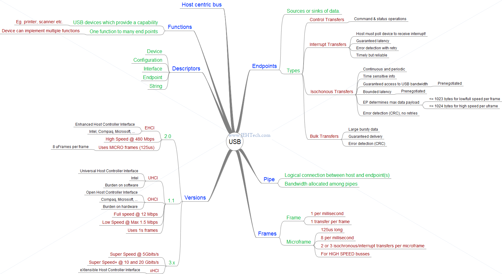
Whirlwind Tour
- D+, D- differential pair for data signalling (2 pairs for USB).
- Tiered star topology.
- All comms (except sometimes USB 3) initiatied by host. The USB is a polled bus. The Host Controller
initiates all data transfers.
Each transaction begins when the Host Controller, on a scheduled basis, sends a USB packet describing the type and direction of transaction, the USB device address, and endpoint number. This packet is referred to as the "token packet". The USB device that is addressed selects itself by decoding the appropriate address fields. In a given transaction, data is transferred either from the host to a device or from a device to the host. The direction of data transfer is specified in the token packet. The source of the transaction then sends a data packet or indicates it has no data to transfer. The destination, in general, responds with a handshake packet indicating whether the transfer was successful.
USB establishes a 1 millisecond time base called a frame on a full-/low-speed bus and a 125 µs time base called a microframe on a high-speed bus. A (micro)frame can contain several transactions. Each transfer type defines what transactions are allowed within a (micro)frame for an endpoint. Isochronous and interrupt endpoints are given opportunities to the bus every N (micro)frames.
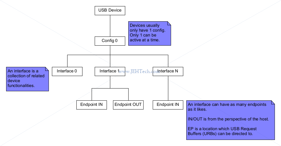
- Devices are self-describing using descriptors.
- USB data transfers occur through a series of events called transactions. Transactions are conducted within a host-controlled time
interval called a frame. The length and frequency of the transactions depend upon the transfer type being used for an endpoint.
Transfer types:- Interrupt. [1 per n frames].
- USB can't really do interrupts as the host must poll >devices.
- Guaranteed brandwidth - reliable (CRC/handshake).
- E.g. mouse.
- Isochronous. [1 per frame].
- Time sensitive, guaranteed brandwidth, not reliable.
- Periodic, continuous communication between host and device.
- Guaranteed access to USB bandwidth with bounded latency.
- Can only be used by full-speed and high-speed devices.
- Control. [n per m frames].
- Best effort bus access. Reliable.
- Used to configure a device at attach time and can be used for other device-specific purposes, including control of other pipes on the device.
- Intended to support configuration/command/status type communication flows.
- Transactions involved:
- Setup bus transaction - move requestion information from host.
- >=0 data transactions - direction has set in setup transaction.
- Status transaction.
- Bulk. [n per m frames].
- Good effort bus access - reliable (CRC/handshake).
- Generally large and bursty.
An endpoint is a uniquely identifiable portion of a USB device that is the terminus of a communication flow between the host and device. Each USB logical device is composed of a collection of independent endpoints. Each logical device has a unique address assigned by the system at device attachment time. Each endpoint on a device is given at design time a unique device-determined identifier called the endpoint number. Each endpoint has a device-determined direction of data flow. The combination of the device address, endpoint number, and direction allows each endpoint to be uniquely referenced. Each endpoint is a simplex connection that supports data flow in one direction: either input (from device to host) or output (from host to device).
- Interrupt. [1 per n frames].
Transaction Limits
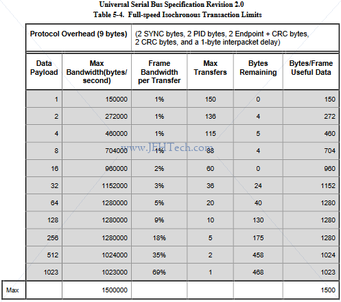
To the left is a screenshot of "Table 5-4. Full-speed Isochonous Transaction Limits" from the USB 2.0 standard [Ref].
To see how the limits are arrived at lets consider transfering the maximum isochronous packet size of 1023 bytes. Given the 9 bytes header we have a total of 1032 byes. At 12 Mbps, which is 1.5MBps, 1032 bytes takes 688uS. Thus in the 1 millisecond frame time allocated we can only do one such transfer. 312uS are not used, which is equivalent to 468 bytes.
The standard has similar tables for high speed and low speed transfers too...
If you were to look at "Table 5-5. High-speed Isochronous Transaction Limits", you might see something that puzzels you at first. Remember that high speed packets can be up to 1024 bytes. But, the table dows payloads of 2048 bytes and 3072 bytes as well. Why? The reason is that HS devices can specify 1, 2 or 3 transfers per microframe, hence the higher effective payloads.
Charging
References
Notes
- Original USB 1&2 (prior to BC1.1): Two power source types:
- 5V, 500mA (high power)
- 5V, 100mA (low power)
- 5V, 2.5mA (suspended)
- Battery Charging Specification, Rev 1.1 (BC1.1). Defines additional power sources:
- Standard downstream port (SDP):
- Power same as Original USB 1&2.
- Identify by detecting that the USB data lines, D+ and D-, are separately grounded through 15 KOhms (still needs to enumerate).
- Charging downstream port (CDP):
- Can supply up to 1.5A (before enumeration)
- Identify by means of a hardware handshake implemented by manipulating and monitoring the D+ and D- lines before turning the data lines over to the USB transceiver.
- Dedicated charging port (DCP):
- Power sources that no not enumerate, like wall warts.
- Supply up to 1.5A.
- Identified by a short between D+ to D-.
- Standard downstream port (SDP):
- BC1.2 -- Oct 2011
- Allows DCPs to output more than 1.5A
- Increase minimum CDP current to 1.5A. Without change, PDs had to draw less than 500mA.
- And more but those 2 seemd to be the most relatable to abolsulte current draws.
- Accessory Chargin Adapters (ACA)
- For USB On-The-Go devices.
- Charge USB peripheral whilst having access to it.
- USB Power Delivers (USB-PD)
- July 2012
- High power devices (e.g. laptop etc) can use PD aware USB cables to deliver > 7.5W.
The Analog.com article (see references) had the best charger detection process section:
- VBUS detection: Thee voltage and ground pin contact first. VBUS detect before charger detection can start.
- Data contact detection (DCD): Ensure data pins connect before detecton starts to avoid incorrect identification.
- Primary charger detection: Differentiation between SDP port and CDP/DCP ports.
- Secondary charger detection: Differentiate between CDP v.s. DCP.
- CDP charge current limit: Determine whether high current charging is possible.
From the Anlog.com website:
