Linker Script Notes
Page Contents
GNU Linker Files
References
- From Zero to main(): Demystifying Firmware Linker Scripts
- The Most Thoroughly Commented Linker Script in The World
- Executable and Linking Format (ELF) Specification Version 1.2
- ARM ELF File Format
- Basic Linker Script Concepts
- LD docs
- RedHat: Using the GNU Linker
Anatomy
LD files contain the following:
- Memory layout: what memory is available and where.
- Section definitions: where different program sections (code and data) should be placed in memory.
Convention:
.textfor code and constants,.bssfor uninitialised data,.stackand.datafor initialised data. - Options: commands for architecture, entry point etc.
- Symbols: variables injected into program at link time.
Memory Layout
In general the memory layout is defined using the MEMORY specification, which is normally found near the top of the linker file. It has the following generic structure:
MEMORY
{
  name [(r|w|x|a)*] : ORIGIN = origin, LENGTH = len
  ...
}
For example, the MEMORY section generated by the STM32Cube IDE for the ST Nucleo L552ZE, which is an ARM Cortex-M33, is as follows:
MEMORY
{
  RAM   (xrw) : ORIGIN = 0x20000000, LENGTH = 192K
  RAM2  (xrw) : ORIGIN = 0x20030000, LENGTH = 64K
  FLASH (rx)  : ORIGIN = 0x08000000, LENGTH = 512K
}
This specification tells the linker:
- There is a memory region, to which the name "RAM" is given, that starts at
0x2000_0000and ends at0x2002_FFFF. It is readable, writable and executable. - There is a memory region, to which the name "RAM2" is given, that starts at
0x2003_0000and ends at0x2003_FFFF. It is readable, writable and executable. - There is a memory region, to which the name "FLASH" is given, that starts at
0x0800_0000. It is readable executable but not writable.
Note: that the linker doesn't understand what "RAM", "RAM2" or "FLASH" means other than the fact that they are memory regions. The strings "RAM" et al are just labels that can be used to refer to those regisions of memory later on in the LD file.
Sections
All of the object files contain various sections. These are the input sections. For example, by default, all of the code in each object file is contained in a section called .text.
There are 3 common types of section:
.text: This holds the code - i.e., executable instructions..bss: This holds uninitialised global data. To meet the C(++) spec, this data should be zeroed beforemain()is entered..data: This holds initialised global data.
The linker file defines a set of output sections that include arbitrary input sections. I.e., the input sections are mapped to output sections, which are mapped to various physical memory locations.
To define and add a section to a memory region, the general syntax is:
SECTIONS
{
    .output_section_name [address] [BLOCK(align)] [(type)]: <-----------+
    {                                                                   |
        file_name(section_name_in_file) --------------------------------+  << Any filename and input section(s) within matching
    } [> memory_region_name] [AT> load_addr ]                                 these patterns get put into the .section_name section.
}
In the above, the files being linked are inputs and the sections they contain are input sections. The result of the linking, i.e., the single binary, also contains sections, sometimes called output sections.
Let's imagine a simple, dummy linker file:
MEMORY {
  MEM1 ([rwx]+) : ORIGIN = 0x>???????, LENGTH = ???K
  MEM2 ([rwx]+) : ORIGIN = 0x>???????, LENGTH = ???K
  MEM3 ([rwx]+) : ORIGIN = 0x0???????, LENGTH = ???K
}


SECTIONS {
   .output_1 {
      *_a.o (.text*)
      * (.other_named_section)
   } > MEM_1

   .output_2:
   {
      * (.special_text*)
   } > MEM_1

   .output_3:
   {
      *_b.o (.text*)
   } > MEM_2

   .data:
   {
      * (.data)
   } > MEM_3
}
It would layout the image something akin to this:
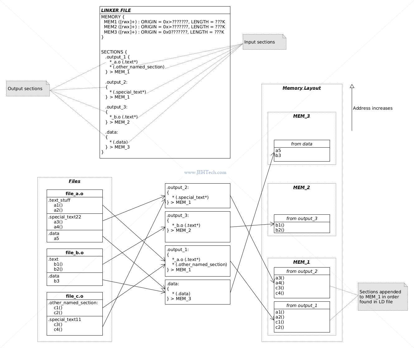
Looking at how some of the input sections are mapped to output sections:
-
In the
output_2section, the pattern*(.special_text*)says "match all object files and include from the matched object files all sections who's name start with "special_text".
Thus the file selector, being the wildcard, selects all the object filesfile_a.o,file_b.o, andfile_c.o. From this set of object files the sections matching.special_text*are.special_text22and.special_text_11. Thus, these two sections are selected and their contents appended into the memory regionMEM_1. -
The sections
.output_1and.output_3show how sections with the same name, from difference object files, can be mapped to different memory regions.
For example, the section.output_1takes the.textsection only from files matching the pattern*_a.o. Thus, only the.textsection fromfile_a.ois selected and appended to memory regionMEM_1. -
And so on...
Section Garbage Collection & Keeping Files
The linker is capable of pruning all unused sections from the final, linked, binary. Note sections and not functions! To ask the linker to do this the --gc-sections options must be passed to the linker. When doing the build and link from the one command the option usually looks like gcc ... -Wl,--gc-sections ....
Why is this useful? The scenario I've encountered this in is for pruning unused functions (and data). To do this the compiler has a little trick up its sleave: because the linker can only prune sections, it can put each function (and data item) in its own section. To tell the compiler to do this, the flags -fdata-sections -ffunction-sections.
In the rather contrived LD file seen above, if we use the flags -fdata-sections -ffunction-sections, we get the following:
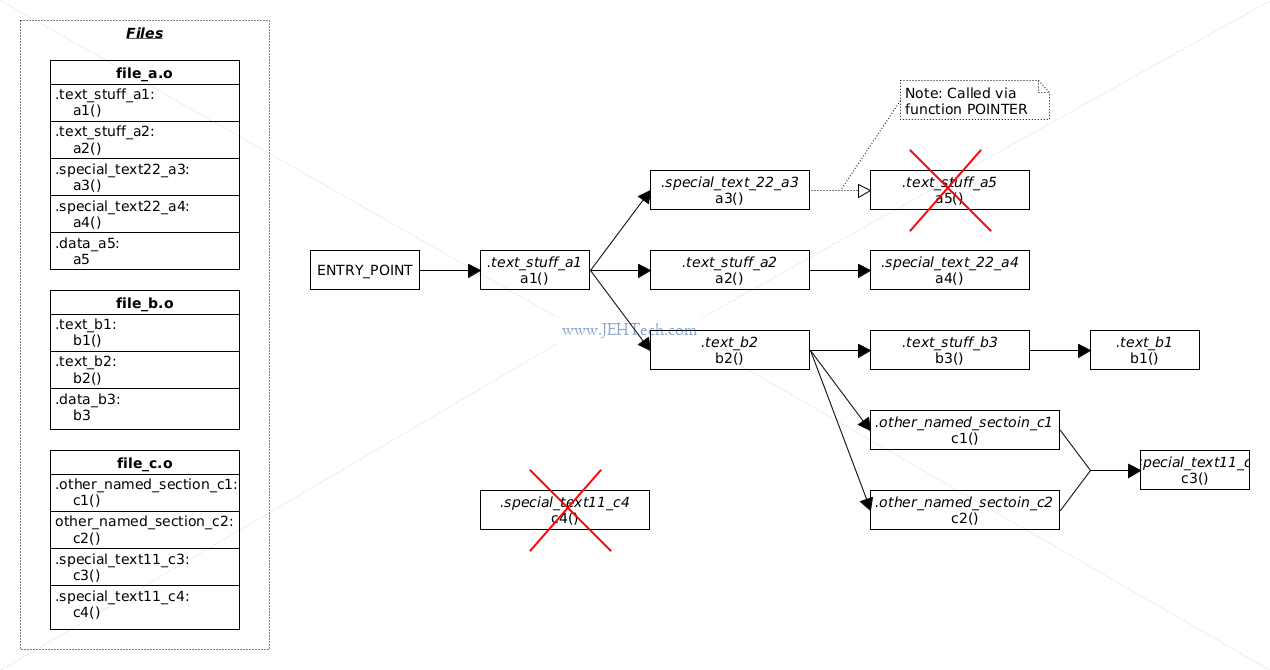
Each function has been placed in its own section. The linker can generate a call graph between sections, and thus, in this case between functions. Any node that is not part of the call graph is unused and therefore garbage collected: not included in the output.
Note a small caveat! The section .test_stuff_a5 and thus the function a5() has been garbage collected (and thus the link will fail). Why is this? It is because it appears that the linker cannot track functions called by pointer! This was an interesting problem I had when trying to prune unused mock functions from Ceedling tests: the test functions are all called via function pointer and so a naive garbage collection just got rid of all the test functions (see below).
The KEEP directive is also interesting and will help us tell the linker not to discard .test_stuff_a5 in the above example. The directive is used when the linker does garbage collection of unused sections and specifically tells the linker never to discard the sections annotated by KEEP.
So why are the following useful? One example use I had was using Ceedling. Ceedling outputs an absolute ton of mocked methods for unit tests, only a small fraction of which I actually used in my tests. When running on a memory constrained target this was a problem as including unused functions bloated the .text section size to the point that some tests would not fit in flash. How to overcome this? Get the linker to discard unused functions. The catch? The linker can only do things at the section level of granularity, so to work around this we must tell GCC to put each function in its own section using the -ffunction-sections command line option.
EXCLUDE_FILE (test_*.o) *(.text*)
KEEP(test_*.o(.text*))
The first line includes all .text* sections, except those sections found in files named test_*.o. The linker can prune these sections as it sees fit.
The second line, test_*.o(.text*), selects all .text sections from files matching the pattern test_*.o - the opposite of above. The KEEP specifier tells the linker that although it has been instructed to garbage collect unused sections, it may not garbage collect the .text sections from files matching the pattern test_*.o. The reason for this is that if we don't specify this it will garbage collect almost everything. The reason for this is that the main Ceedling test runner, runs the test functions by calling them through a function pointer. The linker cannot track this so the call graph it would otherwise generate would not include any tests... fun!
Therefore, what we're saying is that the linker is free to garbage collect everything it likes, except the test functions themselves - we force it to know something about the call graph it couldn't otherwise.
The compiler flags that were added to the target ceedling YAML are what enable the garbage collection by instructing the compiler to put every function in its own section, which is what then allows the linker to garbage collect, as it can only garbage collect by section.
One word of caution: putting each function into its own section may actually increase the function size! [Ref].
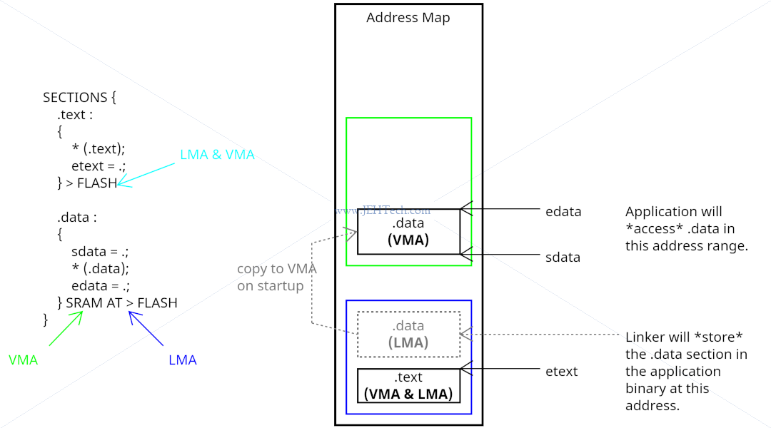
VMA and LMA
Every section has a load address (LMA) and a virtual address (VMA). The linker uses VMA addresses to resolve symbols.
Every loadable or allocatable output section has two addresses. The first is the VMA, or virtual memory address. This is the address the section will have when the output file is run. The second is the LMA, or load memory address. This is the address at which the section will be loaded. In most cases the two addresses will be the same. An example of when they might be different is when a data section is loaded into ROM, and then copied into RAM when the program starts up (this technique is often used to initialize global variables in a ROM based system). In this case the ROM address would be the LMA, and the RAM address would be the VMA.
In summary: * VMA - Address used during execution. * LMA - Address used to store.
Define Registers In LD File
A nice alternative to defining register locations in C files using #define's, the location can be put in
linker files.
Means that, for example, OS doesn't need to be re-compiled for different targets, just re-linked. So, when there is a lengthy recompile time, being able to just link against the correct linker file for the platform gives both a more efficient production time but also less coupling to the locations of devices in the memory map.
Say the SPI interface registers are at 0x8000_0000 on one platform and 0x9000_0000 on another. Its the
same SPI interface, just at different locations. Rather than re-compile for different targets so that
different #define's are compiled in, if the definitions are in the linker file, then only a re-link
is required.
In the linker file:
...
SECTIONS {
   ...
   .SPI_Interface_1 0x8000000 : {
      spi_1_driver_file.o (.SPI_1_SECTION)
   }
   ...
}
In the C file spi_1_driver_file.c:
typedef struct spi_registers_tag {
   uint32_t reg1;
   ...
} spi_registers_t;

volatile spi_registers_t SPI_1 __attribute__((section("SPI_Interface_1)));
Then the variable SPI_1 can be accessed normally in code to read and write to the registers defined in the structure.
TODO
TODOS:
- ALIGN - padding vs section start
- PROVIDE
Referencing Linker Script Symbols From C Code
You cannot access the value of a linker script defined symbol - it has no value - all you can do is access the address of a linker script defined symbol.
What this means is that the symbols provided in the linker script are not backed by their own memory like a symbol in normal C code would be.
This means that if you define a symbol in your linker file called, for example, mysec_start as so:
SECTIONS {
   ...
   .mysec {
      .= ALIGN(8)
      mysec_start = .
      *(.mysec*)
   }
   ...
}
If you declare it in C as follows:
extern uintptr_t mysec_start;
You must take the address of mysec_start to get the address of, what in this case is, the section start.
Lets say that upon link, the linker assigns the value 0x8000_0000 to mysec_start. In C the following is true:
&mysec_start == 0x8000_0000

mysec_start == What ever is in memory at the address 0x8000_0000