RS232/RS422/RS485
Page Contents
RS232, TTL and CMOS Voltage Levels
Serial v.s. Voltage Levels
A serial interface does not necessarily imply a voltage level, which I found quite interesing. RS232, technically, as a standard just defines the voltage levels that represent mark and space, and potentially the type of connector used (9 or 25 pin D connector). Thus, technically, when one says "RS232" one is talking about voltage levels only, but it is usually taken to mean "RS232 voltage levels applied to the serial protocol" - a slight conflation, and one that I realise I make many times later on in this page :/
Conversely, the serial protocol defines the meaning of start/stop bits, baud, parity and signals such as "request to send". It doesn't specify voltage levels.
This means that, for example, an Arduino can output a serial-protocol bit stream at 5V (TTL). To connect this to a serial port on a PC (uses RS232 volatage levels) a transceiver chip is required. The serial protocol remains the same, its just the voltage levels that change.
This is why, when connecting serial lines to equipment, different voltage levels may need to be accounted for. TTL and CMOS are the two types of circuit with associated logic levels that you may need to convert to and from.
RS232
RS232 defines the voltage levels as +5V to +15V for a space and -5V to -15V for a mark at the transmitter, and to account for signal attenuation, +/-3V to +/-13V at the receiver. [Ref].
TTL
TTL logic is transistor-to-transitor logic where the ciruits make use of transistors for both the logic and amplification functions. It has a reasonable resistance to noise and a high switching rate. It draws more current than CMOS circuits though [Ref].
TTL circuits use 5V. The signal is low between 0V and 0.8V and high above 2V. Between 0.8V and 2V the signal is undefined. When receiving a signal a margin is added to these values to account for possible noise. Normally 0.4Vs of noise accounted for so low is defined as 0V to 0.4V and high as 2.4V or more (up to 5V).
TTL circuits are constructed using NPN and PNP bipolar transistors.
I'm not sure if the TTL circuit type and voltage levels defined by "TTL" were ever linked by the type of transistor
being used. Nowadays it seems like it is a pure voltage level definitions as CMOS and TTL circuits will normall use
TTL voltage levels. As a friend of mine told me, most chips are CMOS now, but ensuring that they comply with
the older "TTL standard" voltage levels means that you can take pretty much anything from any manufacturer
and connect them together if the voltage standards match
.
CMOS
Draws less current than TTL. Has wider noise margins normally. Can go from 0V to 5V but can also go from 0V to 3V3 for example, and what constitutes a low or high signal is based on percentages of the high voltage [Ref].
CMOS circuits are constructed using NPN and PNP MOSFETs.
Summary
| Type | Vlow | Vhigh | Notes |
| RS232 | +3V to +13V | -3V to -13V | At the receiver |
| TTL | 0V to 0.8V | 2V to VCC | VCC = 5V, tolerance = 10%. |
| CMOS | 0V to 1/3VDD | 2/3VDD to VDD | VDD = supply voltage |
Single Ended (Unbalanced) v.s. Differential Signals (Balanced)
Single ended signals are measured with respect to a common ground between transmitter and receiver. Only one wire is nedded for one signal (and one for common ground).
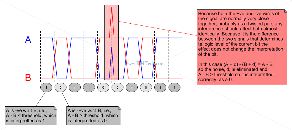
Differential signals use two wires, A and B, for the one signal (and another wire for ground reference). The signal is high or low depending on the difference between the two received voltages. When A is +ve with respect to B, i.e., A > B, the signal represents a 0, or space. When A is -ve with respect to B, i.e., A < B, the signal represents a 1, or mark. We can see that the lines produce complementary (opposite) output signals.
Although an extra wire is required, the signal becomes far more robust to noise as local signal interference should affect both wire equally, so will be eliminted when the difference between the two volatages is taken:
RS232
Introduction
RS232 links 2 devices together in a point-to-point fashion. Historically the terminal end of the link is the Data Terminal Equipment (DTE). This would have been your PC, for example. It is the source and destination of the data. The other end is the Data Circuit-terminating Equipment (DCE). This would have been an old-school modem, for example. The DCE is responsible for sending the data somewhere... i.e., it was what did the communications.
Thats the history. You can connect any two devices together - it doesn't matter which is the DTE and which is the DCE so long as there is one of each.
Signal Meanings/Functions
All signal names are from the perspective of the DTE.
RS232 can be setup with a minimum of 3 signals:
+-------+                           +-------+
|       +---------TD/TX/TXD-------->+       |
|       |                           |       |
| DTE   +<--------RD/RX/RXD---------+ DCE   |
|       |                           |       |
|       +<--------SG/GND/SGND------>+       |
+-------+                           +-------+
- TD, or terminal data, a.k.a TX or TXD, transmits data from DTE to DCE.
- RD, or receive data, a.k.k RX or RXD, receives data sent from DCE to DTE.
- SG, or signal ground, is a common groudn shared between the DTE and DCE so that they have common point of reference for measuring the voltages on TD and RD.
The other signals, such as DTR/DRS and RTS/CTS are used for handshaking.
Signal Volatages
The signals use negative logic. A true/high/logic-1 signal (aka mark) is transmitted as -5V. A false/low/logic-0 signals (aka space) is +5V. Thse are the voltages used to drive the signal. However, because, over distances, signa may attenuate (weaken) at the receive +3V and -3V are accepted as low and high values respectively. Thus the RD line from the DTE's point of view uses 3V and -3V.
These are only typical volatests. They can range from +/-3V to +/-15V
Bit Meanings
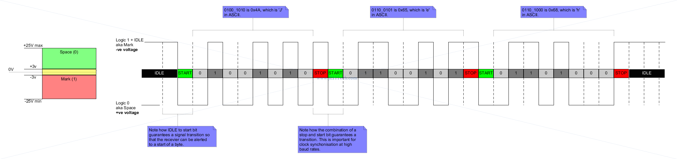
Because RS232 is asynchronous there is no shared clock between the transmitter and receiver. When the transmitter starts the receiver must set its clock to the same baud rate so that it knows when to sample the incoming signal.
The receiver is "primed" by a start bit, which is a logic low or "space" Whilst the line is idle it is held at a logic high, or mark. Normally 8 bits are transferred after the start bit, which are then preceeded, usually by a parity bit and a stop bit.
Why the stop bit? It can be 1, 1.5, or 2 bit periods. It is used, not only to give a period of time before the next start bit can be transmitted, but more importantly to guarantee a transition in the signal level between each byte, which aids clock synchronisation between transmitter and receiver. The stop bit is a mark, or logic high.
The following shows an example of a serial transfer of the text "Jeh" in ASCII with 1 stop bit and no parity:
RS485
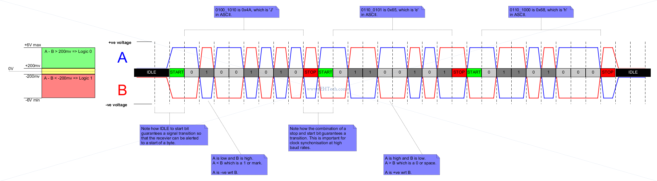
RS485 is most importantly a differential signal, which makes it more robust to noise than the sigle-ended RS232 signal. It can also be transmitted over larger distances before requiring a repeater, and can utilise faster bit rates [Ref].
Like RS232, RS485 will still employ start and stop bits in order to synchronise sender and receiver sampling times and may or may not use parity bits etc. Lets try and re-create the transmission of "Jeh":
Another ability of the RS485 standard is that it can be used to create a half-duplex, multipoint network, because when the line is idle all senders are in a high-impedence, tri-stated state [Ref]. I.e., thge line "floats" and is not pulled either high or low. Therefore, any device on the network can acquire the bus.
How devices acquire the bus is not specified. It can be that one device is a controller and when a client is addressed only it can respond, for example.
RS422
Kinda like RS485 but multi-point rather than multi-drop.