


MPEG
Page Contents
References
- "Digital Video: An Introduction to MPEG-2", B. G. Haskell et al.
- "Telecomminications Handbook" K. Terplan, P. Morreale.
- "Research and Development Report. MPEG-2: Overview of the ystems layer", BBC.
- Transport Stream Overview, Ensemble Designs.
- Packet Timing, Enseble Design.
- "Asynchronous Interfaces For Video Servers", TVTechnology article.
- Timing and Synchronisation In Broadcast Video, Silicon Labs.
- Hakan Haberdar, "Generating Random Number from Image of a Probability Density Function", Computer Science Tutorials [online], (Accessed 09-26-2016).
- Historical Timeline of Viedo Coding Standards, VCodex.com.
- A Biginners Guide for MPEG-2 Standard, Victor Lo, City University of Honk Kong.
- A Guide to MPEG Fundamentals and Protocol Analysis, Tektonix.
- Mastering the Adobe Media Encoder: Critical Concepts and Definitions, Jan Ozer -- This is a really good high level tutorial about bit rates and frame rates, resolution, CBR and VBR and how the inter-relate in terms of the final encoded video quality.
- TOREAD: An ffmpeg and SDL Tutorial, dranger.com
- How Video Works, M. Weise & D. Weynand. ISBN 0-240-80614-X
- FFMPEG Filters.
- Scaling (Resizing) With FFMPEG..
- What Is DVB-ASI?, Ensemble Designs (YouTube video).
- Audio Specifications, Rane Audio Products. [Great little summary of things like THD+N].
To Do / To Read
- https://sidbala.com/h-264-is-magic/
- Chapter 2: Understanding the Application: An Overviewof the H.264 Standard, Scalable Parallel Programming Applied To H.264/AVC.
- http://forum.blu-ray.com/showthread.php?t=121087
- https://en.wikipedia.org/wiki/Dialnorm
- http://www.theonlineengineer.org/DownLoadDocs/Meas%20Dialnorm%20Aeq.pdf
- https://en.wikipedia.org/wiki/Dynamic_range
- https://en.wikipedia.org/wiki/DBFS
- http://www.dolby.com/uploadedFiles/Assets/US/Doc/Professional/38_LFE.pdf
- http://www.dolby.com/us/en/technologies/all-about-audio-metadata.pdf
- http://www.dolby.com/us/en/technologies/dolby-digital.pdf
- http://www.dolby.com/uploadedFiles/Assets/US/Doc/Professional/38_LFE.pdf
- http://www.tvtechnology.com/miscellaneous/0008/a-closer-look-at-audio-metadata/184230
- http://www.tvtechnology.com/audio/0014/what-is-downmixing-part-1-stereo-loro/184912
- http://www.dolby.com/us/en/technologies/a-guide-to-dolby-metadata.pdf
- http://www.dolby.com/us/en/technologies/all-about-audio-metadata.pdf
- http://www.tvtechnology.com/miscellaneous/0008/a-closer-look-at-audio-metadata/184230
- http://www.digitaltrends.com/home-theater/ultimate-surround-sound-guide-different-formats-explained/
- http://www.popenmedia.nl/themas/Readers/Geluid/209_Dolby_Surround_Pro_Logic_II_Decoder_Principles_of_Operation.pdf
- http://educypedia.karadimov.info/library/208_Dolby_Surround_Pro_Logic_Decoder.pdf
- http://www.acoustics.salford.ac.uk/placement/chaffey.pdf
- http://www.soundandvision.com/content/surround-decoding-101#zxxiKtKwQVJ6KEDC.97
- https://en.wikipedia.org/wiki/Auditory_masking
- http://legeneraliste.perso.sfr.fr/?p=echelle_log_eng -- log scales - proprtionality
- https://www.safaribooksonline.com/library/view/handbook-for-sound/9780240809694/010_9781136122538_chapter2.html#sec2.2
- Excellent huffman coding tutorial: https://www.youtube.com/watch?v=ZdooBTdW5bM
- https://www.youtube.com/watch?v=5wRPin4oxCo
- Run length coding: https://www.youtube.com/watch?v=ypdNscvym_E
- https://www.youtube.com/watch?v=rC16fhvXZOo
- https://www.researchgate.net/publication/220931731_Image_quality_metrics_PSNR_vs_SSIM
- http://repositorio.ucp.pt/bitstream/10400.14/4220/1/lteixeira.2008.conference_ICCCN_IMAP08.pdf
- https://www.gearslutz.com/board/post-production-forum/184636-definitive-explanation-29-97-23-98-timecode.html
- http://wolfcrow.com/blog/understanding-terminology-progressive-frames-interlaced-frames-and-the-field-rate/
- https://www.gearslutz.com/board/post-production-forum/184636-definitive-explanation-29-97-23-98-timecode.html
- http://www.paradiso-design.net/videostandards_en.html
- http://datagenetics.com/blog/november32012/index.html
- https://codesequoia.wordpress.com/2014/02/24/understanding-scte-35/
- http://pdfserv.maximintegrated.com/en/an/AN734.pdf AND http://www.ni.com/white-paper/4750/en/
- https://www.provideocoalition.com/field_order/
- https://ultrahdforum.org/wp-content/uploads/2016/12/Ultra-HD-Forum-Deployment-Guidelines-v1.2-December-2016.pdf
- Color: http://poynton.ca/notes/colour_and_gamma/GammaFAQ.html#gamma
- Color: https://poynton.ca/PDFs/coloureq.pdf
- Color: https://help.prodicle.com/hc/en-us/articles/115015911188-Color-Space-and-Transfer-Function
- https://www.fortinet.com/content/dam/fortinet/assets/white-papers/wp-ip-surveillance-camera.pdf
Glossary
| Acronym | Meaning | Brief Description |
| ATSC | Advanced Television Systems Committee | An international, non-profit organization developing voluntary standards for digital television. |
| NTSC | National Television System Committee | NTSC is the video system or standard used in North America and most of South America. |
| PAL | Phase Alternating Line | A colour encoding system for analogue television used in broadcast television systems. |
| SECAM | Sequentiel couleur a memoire - French for "Sequential colour with memory" | |
| SSM | Source Specific Multicast |
A method of delivering multicast packets in which the only packets that are delivered to a receiver are those originating from a specific source address requested by the receiver. By so limiting the source, SSM reduces demands on the network and improves security-- From WikiPedia. |
| UPID | Unique Program Identifier | |
| VUI | Video Usability Information | |
| SEI | Supplementa Enhancement Information | |
| PPS | Picture Parameter Set | Introduced in H.264/AVC in response to the devastating effects of a loss of the sequence header and picture header. [Ref] |
| SPS | Sequence Parameter Set | Introduced in H.264/AVC in response to the devastating effects of a loss of the sequence header and picture header. [Ref] |
Video Introduction
The Basics
Video is a series of still images that are displayed quickly enough, one after the other, so that the human eye/brain percieves only continuous motion and not individual stills. Each still image is called a frame.
First video screens were CRTs. An electron beam was "fired" at a screen which contained rows of pixels. A pixel was phosphorous and would illuminate when the electron beam hit it. By scanning the electron beam horizontally for each line a picture could be created. The is shown in the image below (crudely).
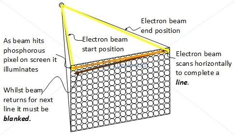
By scanning quickly enough, an image can be "painted" on the screen. Each pixel would fluoresce for a certain amount of time so by scanning image after image on the screen quickly enough, the human eye/brain perceives a moving picture without any flicker. The eye retains an image for somewhere between $\frac{1}{30}$ and $\frac{1}{32}$ seconds. This is known as the persistence of vision. This is why the the frame rate has to be greater than roughly 32Hz, otherwise flicker will be perceived.
Consumer video displays between 50 and 60 frames per second. Computer displays typically display between 70 and 90 frames per second. The number of full frames per second is called the frame rate. It is sometimes refered to as the temperal resolution of the image: how quickly the image is being scanned.
The Early Standards
Very early TV standards were developed by the NTSC (named after National Television System Committee) in the Americas and in Europe a system call PAL was used. France and Soviets used SECAM.
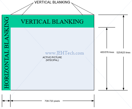
NTSC uses 30 fps and 525 lines per frame. 480 lines actively used. 4:3 aspect ratio.
PAL & SECAM use 25 fps and 625 lines per frame. 580 lines actively used. 4:3 aspect ratio (orig) or 16:9 aspect ratio (later).
Not all of the lines are actively used due to vertical blanking. Horiztonal blanking occurs before and after each line. As said, the blanking information is part of the early video signals:
Interlaced v.s. Progressive
But wait, haven't we just said that persistence of vision lasts between $\frac{1}{30}$ and $\frac{1}{32}$ seconds? Yes, and that is a problem. At 30 fps for NTSC and 25 fps for PAL/SECAM, it is possible that visual flicker could be seen. The frame rate needs to be increased. This is why interlaced video was invented. By transmitting the odd lines and then the even lines, for the same amount of data, the frame rate can be doubled, which helps eliminate the effects of flicker. A frame is split up into the odd lines and the event lines, each set of lines being transmitted and displayed seperately. Each set of lines is called a field. This process of field-by-field scanning is called interlaced scanning. The higher frame rate gets traded off against slightly worse vertical flicker for fast moving objects.
Modern compression and data rates mean that interlaced scanning isn't needed as much so most displays use progressive scans where the frame is just the frame - both odd and even lines. The display fills the image line after line. This is prefereable because it is more robust to vertical flicker.
This is why we see the "i" and "p" to resolutions. For example, for 720x480i, the suffix "i" means interlaced and for 720x480p, suffix "p" means progressive.
Blanking & Ancillary Data
References:
- Understanding & Troubleshooting Closed Captions, Tektronix.
When the electron beam has finished one line, it must return to the start of the next line. Whilst it is doing this it must be turned off, otherwise it would re-paint pixels it shouldn't on its return path. This turning-off-during-return is called blanking. There are two forms of blanking:
- horizontal blanking, and
- vertical blanking.
Horizontal blanking is used to disable the electron beam as it travels from the end of one line down to the start of the next line. Vertical blanking is used when an entire frame has been painted and the beam has to move back to the top left of the first scan line.
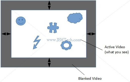
Blanking information is part of the video signal. This means that there is "blank" data transmitted during the blanking interval which not displayed. This is done to give the electron beam enough time to be turned off before it returns to the top of the screen.
Vertical sync, VSYNC, is timing info indicating when new image starts. Horizontal sync, HSYNC, is timing info indicating when new scan line starts.
None of the data sent during the blanking intervals is displayed. This means the data can be used to carry other information, called either ancillary data (ANC) or blanking information. The vertical blanking signal data is refered to as VBI (Vertical Blanking Information). The horizonal blanking information is refered to as HBI (Horizontal Blanking Information) .
VBI/HBI was part of the analogue signal standards. More modern digital signals have kept the blanking information. The corresponding terms are VANC (Vertical Ancillary (Data)) and HANC (Horizontal Ancillary (Data)).
For example, closed caption data can be sent as part of the VBI or VANC data. Other ancillary data is sent is part of the horizontal blanking.
Ancillary (ANC) data is a means of embedding non-video information, such as audio and metadata, in a serial digital transport stream. Ancillary data packets are located in horizontal (HANC) or vertical (VANC) blanking of a video signal. HANC is used to embed uncompressed audio data in the SDI or HD-SDI stream. VANC is used to embed low-bandwidth data -- information updated on a per-field or per-frame basis. Closed caption data (CCD) and Active Format Description (AFD) are examples of metadata stored as VANC. SMPTE 291m describes the details of Ancillary data packet structures.
Ancillary data packets include following fields (non-exhaustive!):
- DID - Data IDentifier - Gives type of ancillary data. If no SDID gives 1 word data identification, otherwise 2 word data identification.
- SDID - Secondary Data IDentifier - Only valid with DID to give a two word data identification.
Generally, it seems that the upper VANC and "front" HANC regions are used to encode ANC data. This is why sometimes you will see diagrams such as the following [Ref]. It only shows the upper VBI and left HBI. I initially found this confusing because I thought it implied the onther blanking areas didn't exist - they do as was cleared up when I asked about this on SO [Ref].
Digital Standards
The ATSC standard, named after the Advanced Television Systems Committee, is for digital broadcast. I find the "A" really annoying because it makes me think analogue. It isn't! This is a digital standard. It is, like NTSC, an American standard, mostly used in North America.
In the same way that we had the NTSC and PAL standards, the European equivalent of ATSC is DVB-T, which stands for Digital Video Boardcasting - Terrestrial.
The image below shows where the different digital standards are used (ref: EnEdC [Public domain], via Wikimedia Commons).

SD v.s. HD v.s. 4K v.s. Ultra HD
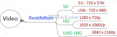
SD stands for Standard Definition. SD gives us the level of detail of an analogue TV, as described above. In Europe we got 576i lines and in America 480i lines giving resolutions of 720×576 and 720×480 respectively. You may want to read the section 'Aspect Ratios v.s. Resolutions' if you're wondering how the different aspect ratios are giving us a 720 width!
HD stands for High Definition. It's essentially SD with more pixels. HD comes as 720p, 1080i, and 1080p. Most modern TVs use progressive scanning as it has less flicker problems.
720p = 1280 x 720. 1080p = 1920 x 1080
4K is Ultra HD = 3840 x 2160p.
HEVC
HEVC stands for High Efficiency Video Coding. It is the successor to H.264. It is a compression standard.
Supplemental enhancement information (SEI) and video usability information (VUI) carry extra information.
HDR
HDR stands for High Dynamic Range. Provides better contrast and color accuracy (expands the range). Not a resolution thing. uses Wide Colour Gammut.
Misc comparison
https://wolfcrow.com/blog/understanding-mpeg-2-mpeg-4-h-264-avchd-and-h-265/
S-Log
Tone repoduction scheme for the high-lights and low-lights. Allows good expose in bright as well as dark parts of image, giving better detail and contrast.
The exposure values with which we measure light are not linear
[Ref]. But if we record the voltage of a digital camera's photo dector linearly we will asign more bits to some "exposure stops" than others. This is where a log scale can be applied to even this out.
Aspect Ratios v.s. Resolutions
Oh dear! Lets take NTSC, for example. We've said it has an aspect ratio of 4:3, but if this were the case, with 480 lines, we should have 640 pixels per line. Yet we've said the standard gives us a resolution of 720x480. What gives? This Wikipedia article explains it. It appears our signal is transmitted to satisfy the SDI bandwidth and I'm guessing this is where the 720 width is coming from. The display then decodes this and somehow displays the image in the display's actual aspec ratio. For example, NTSC 480i has a resoltuion of 720x480. But with 480 lines and an aspect ration of 4:3 it is displayed as 640x480. For SD TV this gives rise to something called the pixel aspect ratio.
ASI / SDI
ASI stands for Asynchonous Serial Interface. It is a compressed form of an A/V signal and is really just an encapuslation method in that it carries data between two points and is often used to encapsulate MPEG transport stream data. It carries data at a constant bit rate of 270 Mbps which results in a payload rate of 213 Mbps [Ref]. ASI can be used to transmit multiple programs.
ASI is a unidirectional tranmission link to transmit data between digital video equipment ... a streaming data format which often carries an MPEG TS ... typically over 75-ohm coax terminated with BNCs ... It is strictly just an interface ... the format for how data is carried ... DVB-ASI is carried at a 270 Mbps line rate ... derived from a 27 MHz byte clock multiplied by 10 bits.
SDI converts a 27MHz parallel stream of a diginal video interface into a 270 Mbps serial stream that can also be transmitted over a 75-ohm coaxial cable. It carries an uncompressed form of an A/V signal and can only transmit the one program.
Audio is transmitted over SDI via the formats ancillary data, which is ... provided as a standardized transport for non-video payload within a serial digital signal; it is used for things such as embedded audio, closed captions, timecode, and other sorts of metadata...
.
My understanding is that SDI is just a "signal" encapsulation format for transmission over a serial coaxial. Using SDI original (aalogue) production content can be transmitted, but digital standards MPEG-2 streams can also be transmitted.
Subtitles / Closed Captions
References:
- Introduction to Closed Captions, Adobe Technical Paper.
- EIA-608 and EIA-708 Closed Captioning , Sarkis Abrahamian
- What’s the Difference Between CEA-608 (Line 21) Captions & CEA-708 Captions?, Emily Griffin
- SCTE 20 2012 - Methods For Carriage Of CEA-608 Closed Captions And Non-Real Time Sampled Video.
- ANSI/SCTE 21 2001R2006, Standard For Carriage Of NTSC VBI Data In Cable Digital Transport Streams.
The terms seem interchangeable as far as I can see, although closed captions might imply better functionaility, like being able to say how the captions should look and where they appear on the screen etc.
Closed Captioning is the process of electronically encoding television speech in such a way that, although it is invisible to the regular viewer, a decoder in the television set (or a special set top box) can decode the spoken word and display it as text in the picture area.
In either case, the general idea is that the text is the equivalent of the audio content, and is such synchronised with the video so that it can be read whilst watching. They assume the viewer is completely deaf and so describes not only the speach but also sounds, for example, describes the ambient music, or animal sounds etc in the scene.
Two closed caption standards are CEA-608 and CEA-708 [Ref] (also refered to as EIA-608/708). The former is the older standard for analogue TV and the latter is the newer standard for digital TV.
In NTSC and SMPTE 259M digital system, captions are encoded onto line 21 of the Vertical Blanking Interval (VBI) ... [In ATSC] The HD-SDI closed caption and related data is carried in three separate portions of the HD-SDI bitstream. They are the Picture User Data, the Program Mapping Table (PMT) and the Event Information Table (EIT).
I.e., NTSC (analogue) CC -> line 21 of VBI
Digital CC -> Picture User Data in MPEG-2 stream.
In modern, digital data streams blanking information is no longer needed really but is still used. Closed captions that would have been carried in the VBI for an analogue signal, can be embedded into MPEG-2 bitstreams, for example. Standards like SCTE-20 [Ref] and SCTE-21 [Ref] define "a standard for the carriage of CEA-608 Closed Captions ... in MPEG-2 compliant bitstreams" [Ref].
The 3playmedia article [Ref] gives a great comparison of the two:
| CEA-608 (Line 21) Captions | CEA-708 Captions |
| Standard for analog television | Standard for digital television |
| Can be transmitted on analog & digital television | Can only be transmitted on digital television |
| Appearance: Uppercase white text on black box background | Appearance: User can control caption appearance. Options include: 8 fonts in 3 sizes, 64 text colors, 64 background colors, background opacity, and edged or dropshadowed text |
| Supports up to 2 languages at a time | Supports multilingual captions |
| Language options are limited to English, Spanish, French, Portuguese, Italian, German, and Dutch (due to lack of special characters) | Supports captions in any language (characters & symbols from every alphabet are supported) |
| Transmitted on Line 21 | Embedded in MPEG-2 streams |
| Caption position is fixed. | Caption position can be changed. The FCC requires that captions be repositioned if they obscure important visual information. |
TODO:
https://www.smpte.org/sites/default/files/section-files/CC%20Complete%20SBE.pdf
https://clearview-communications.com/wp-content/uploads/2017/10/Understanding-the-Video-Signal.pdf
https://www.appliedelectronics.com/documents/Guide%20to%20Standard%20HD%20Digital%20Video%20Measurements.pdf
https://www.intersil.com/content/dam/Intersil/documents/an16/an1695.pdf
https://pdfs.semanticscholar.org/731e/6bb78131ab7ce94e9773790ef656b4d23f2b.pdf
https://www.adobe.com/content/dam/acom/en/devnet/video/pdfs/introduction_to_closed_captions.pdf
https://android.googlesource.com/platform/frameworks/base/+/master/media/java/android/media/Cea708CaptionRenderer.java
https://ecfsapi.fcc.gov/file/6511959011.pdf
https://www.atsc.org/standard/a53-atsc-digital-television-standard/
http://www.atsc.org/wp-content/uploads/2015/03/A53-Part-1-2013.pdf
http://ecee.colorado.edu/~ecen5653/ecen5653/papers/iso13818-1.pdf
MPEG Introduction
Pissing around looking at PCRs etc in Python simulation.
Some terms:
| Acronym | Stands For | Meaning |
| STC | System Time Clock | Time that PU should be decoded and presented to output device. 33-bit. Units of 90kHz. |
| SCR | System Clock Reference | Clock Reference at the PES level. 42-bit. Tells demux what STC should be when each clock reference is received. Units of 27MHz. |
| DTS | Decoding Time Stamp | Type of STC. |
| PTS | Presentation Time Stamp | Type of STC. |
| PU | Presentation Unit | |
| ES | Elementary Stream | Compressed data from a single source (e.g., video, audio) plus data for sync, id etc. |
| PES | Packetised Elementary Stream | An ES that has been split up into packets of either variable or constant length. |
| PSI | Program Specific Information | |
| GOP | Group Of Pictures | |
| T-STD | Transport Stream System Target Decoder | Conceptual model used to model the decoding process during the construction or verification of Transport Streams |
- All streams are byte streams
- Uses packet multiplexing
A 30,000 Foot View
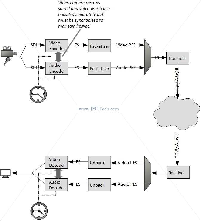
In the above diagram video and audio are recorded. The equipment outputs raw, uncompressed data. The video data will be a series of frames and the audio some kind of stream. Whatever the format that the equipment outputs in, it is the encoder's job to convert this into digitised, compressed data.
You'll note that at the encoder end the audio and video data is encoded seperately. The encoders run off the same clock so that the audio and video encoding remains in sync. The challenge is at the receiver end: the received streams must also be played back in sync (e.g., get the lipsync right or display the correct captions at the right time etc.). Because there is nothing necessarily tying the transmitter and receiver clocks together, and because the transmission media may not result in a constant delay applied to each packet, MPEG defines a way to transmit the clock in the transport stream (TS).
As said, it is the encoder's job to convert this into digitised, compressed data. The reason for this is that the frame rate and resolution required generally means that the data rate coming out of the video equipment, even after digitising, would be far too great to transmit. The bandwidth of most transmission media (e.g., satellite, over the internet etc.) would not be able to support these data rates.
Enter MPEG(-2). It is the job of the encoder to compress the video and audio data and produce an elementary stream which is just a byte stream containing the encoded data. MPEG doesn't actually specifiy what the bytes in the video/audio data means.... that's completely up to the encoder, which is why you will have noticed if that different MPEG files can require difference codecs (codec stands for COder/DECoder). All MPEG does is to define the structure of the stream: i.e., the headers and ordering of frame information etc. This stream may be emitted at a constant or variable bit rate (CBR, VBR respectively).
Once the elemtary stream (ES) is created the packetiser will chunk it up into packets of either constant or variable size. Each packet has a header and payload. The packetised streams are then multiplexed into either a program stream (PS) or a transport stream (TS). I am generally ignoring the program stream in favour of the transport streams in this discussion.
The PS is used in environments that are not noisy. The PS can only support one program. It generally consists of long, variable-length packets. Each packet has a header and a corrupt header can mean an entire packet loss.
The TS, which consists of smaller 188-byte packets, is used in noisy environments as the smaller packet size is more ameanable to error recovery and if one packet is corrupted it is not a great a loss as for a larger PS packet. Note that MPEG does not specify any error recovery mechanism: this must be added by the encapsulating protocol if desired. The TS can contain many programs.
A summary of the flow from ES to PES to TS is shown below.
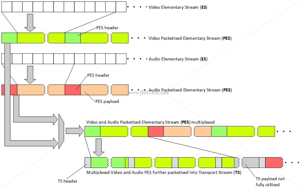
Note how the diagram shows that a TS packet can only contain data from one PES packet, hence the use of some padding at the end of the PES packet didn't fit into an integral number of TS packets - shown by hatched area.
A Receiver At 30,000 Feet
Intro
As was mentioned, the receiver must play back all the streams synchronously to ensure that things like lipsync are correct. How can it do this?
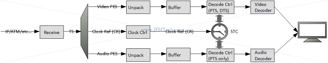
The answer lies in the Program Clock Reference (PCR), the Decoding Time Stamp (DTS) and Presentation Time Stamp (PTS) data that is transmitted with the presentation data (video, audio, subtitles etc). The PCR allows the receiver to estimate the frequency of the encoder clock. The DTS tells the receiver when a Presentation Unit (PU) should be decoded and the PTS tells the receiver when a decoded PU should be presented to the display device.
Shown below, we see that the PTS/DTS are used by the decoders and the PCR is used by the system to control the clock that is driving the decoders so that the system runs at the same frequency and time as the encoder that transmitted this information.
Why do we need to stay in sync? Why should the receiver bother about the frequency of the encoder? Surely if they both have a local clock set to the same frequency there should be no problem. The trouble is that even though two clocks may have the same nominal frequency, their actual or real frequencies will differ by some small amount. Furthermore, these frequencies will not be constant. They will vary with environmental effects such as temperature and change as the crytal ages. They will also exhibit a certain amount of jitter. But, what effect can this have and why should we be concerned? Let's once again look at the overall process...
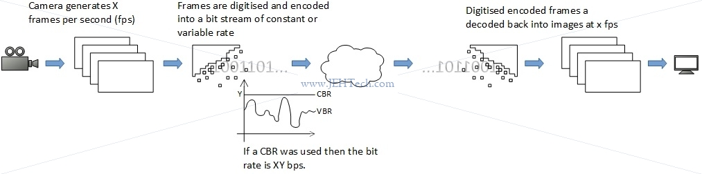
The image above shows that the video equipment is generating X frames per second. Each frame is digitised and then encoded. Each frame will take a slightly longer or shorter time to encode and result in a larger or smaller representation, depending on things like the amount of change from the previous frame, the contents etc. Thus, in general the encoding will result in a variable bit rate. This can be converted to a constant bit rate by simply adding stuffing bytes to each encoded frame so that the bit rate becomes constant.
When we talk about bit rate, we mean the size of the video (or audio) data per second. I.e., in one second how many bits of data do we expect out of the encoder. For example, if the encoder is spewing out data at 500 kbps we know that one second of video data requires 500 kbits of data to transmit it. The frame rate and resolution of the video and the bit rate output from the encoder are related by the amount of compression that the encoder is able to perform: the frame rate cannot be changed, so what determines the bit rate is how much the encoder can compress the frames.
Lets consider CBR as it will make things easier (bit rate is constant). Now lets assume that the transmit-across-the-network stage and the decode stage are all instantaneous. In this case we just decode each frame as we get it and just display it... no problem.
Now lets imagine that the decode is no longer instantaneous. Like the encoder, it may take a little longer to decode some frames and a little less time to decode others. When it takes a little longer, what happens to the frame following right behind it? Clearly we need to be able to queue up that frame rather than dropping it. And what happens if the decoder was really quick on one frame? If the next frame isn't immediately available then the decoder either has to output nothing (so we see a video glitch) or hold on (repeat a frame). Thus is might be an idea to have a few frames in the buffer ready to decode! The same applies to the encoder: some frames might take longer to encode than others, so the decoder also has to decouple from this using a buffer. Incidently the variable encoding time is another reason why PTS timestamps are important.
Then there is the transmission path. That will often have a delay and when going over Ethernet, for example, that delay will vary in a random fashion. So we need a receive buffer to smooth this out too.
Then there is our local clock v.s. the clock of the encoder. If our clock is faster than the encoders, even only by a little bit, we will, over time cause a buffer underrun in the decoder. And if we were even only a little slower, eventually we would have to drop a frame. That's why keeping in sync with the encoder clock and using the DTS/PTS timestamps is important.
Time Sync
Using the PCR timestamps, the receiver can discipline its local oscillator so that the local clock should be, within some tolerance, synchonised (i.e., same frequency and phase) with the encoder's clock. Then once the receiver's clock is correct, the decoder blocks can use the PTS and DTS timestamps correctly to play out video/audio/etc synchronously.
PCR is measured as 33 bits of 90kHz clock and remaining 9 bits of a 27MHz clock, the system clock frequency. The system clock frequency's accuracy is restricted by the the MPEG 2 standard: $$ 27 000 000 - 810 Hz \le \text{system clock freq} \le 27 000 000 + 810 Hz $$
The PCR timestamp is split up into a 9 bit field, the extension, and a 33 bit field, the base, as follows: $$ \text{base} = \frac{\text{system clock freq} \times t(i)}{300} \mod 2^{33} $$ $$ \text{ext} = \text{system clock freq} \times t(i) \mod 300 $$ The quantity $\text{system clock freq} \times t(i)$ just gives the number of clock ticks that have occurred at time $t(i)$ seconds.
For every 300 clock ticks the $\text{base}$ will increment by 1, whilst the $\text{ext}$ increments by 1 for every single clock tick but only ranges from 0 to 299.
So, $\text{ext}$ is like the high precision portion of the clock time stamp. It will go from 0 to 299, and when it wraps back round to 0, $\text{base}$ increments by 1. Thus the PCR is defined as follows: $$ PCR(i) = PCR_{base}(i) \times 300 + PCR_{ext}(i) $$ Where $PCR(i)$ is the number of system clock ticks that have passed at time $t(i)$.
The 27MHz portion of the clock only needs 9 bits to represent its maximum value of 299. So, last question... Why 33 bits for the 90 kHz clock? I'm only guessing but it could be that they wanted to be able to represent (over) a days worth of elaphsed time in 90kHz clock ticks.
Okay, so how do we use these PCR timestamps to acheive at least synchonisation?
If we had a perfect system the clocks at both ends would have zero drift and zero jitter. The communication channel would have a constant, zero delay and never drops or corrupts TS packets. In this case all we are doing is making sure the receiver's clock is running at the same speed as the encoder's clock. It is easy to do. Could we now just take the difference between consequtive PCR timestamps? That would certainly give us the frequency of the encoder's clock as we can assume the gap between each PCR at the encoder was constant. However, this tells us nothing about the receiver clock w.r.t to the encoder clock. The receiver clock could still have a frequency offset. Thus, we need to know when, from the receiver's point of view, each PCR timestamp arrives:
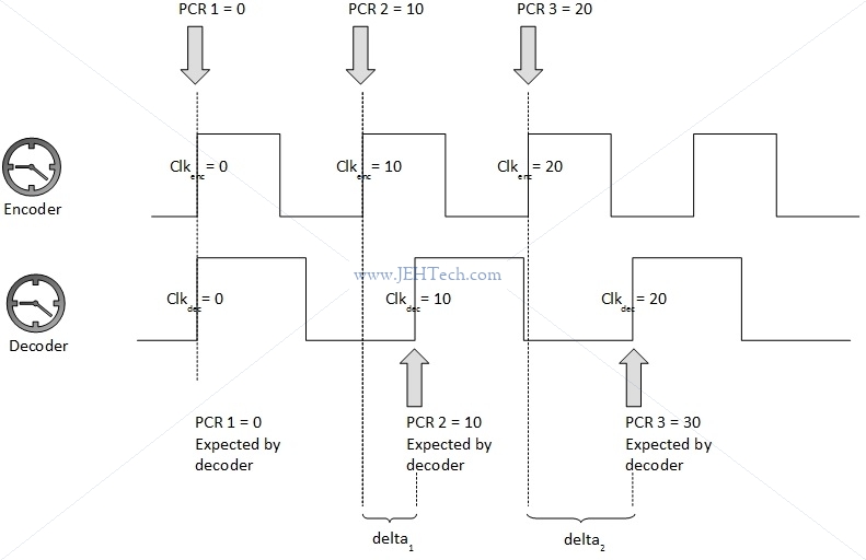
To continue with the example let's imaging that the decoder clock is running about 1.5 times fater than the encoder clock. Thus we might, from the decoder's point of view, receive the following information if we knew that both clocks had a nominal frequency of 10Hz and a PCR is transmitted every second:
| Decoder counts when PCR arrived | PCR count received | Difference |
| 0 | 0 | 0 |
| 15 | 10 | 5 |
| 30 | 20 | 10 |
| 45 | 30 | 15 |
The gradient of the time stamp differences is the frequency offset. Each difference should occur once every 10 counts, by the assumptions we've made, so we know that the gradient difference is 0.5. Therefore the decoder can figure out it is 1.5 times faster that the encoder and correct for this. To begin with, if the frequency offset was very large the decoder might "jump" it's clock frequency to be in the same "ball park" as the encoder, and from there start to align, probably using some kind of control loop, usually PI (Proportional Integral) control.
That didn't seem so bad, but unfortunately we don't live in a perfect world. In reality both the encoder and decoder clocks will have a certain frequency drift from their nominal frequencies and will also suffer from jitter. When the encoder clock wanders, the decoder should follow, but in the reverse situation, where the decoder wanders but the encoder does not, the decoder should detect this and correct it's wandering quickly. For both, the jitter should be filtered out and ignored as much as possible. The third variable is the transmission media. It may have a delay, and most probably this delay is not constant - another source of jitter! It may also drop or corrupt packets so we might not receive all of the timestamps and some may be received out of order and the decoder unit as a whole has to be able to cope with this.
Let's not get so complicated so quickly. Now lets imagine a slightly less perfect system. The encoder and decoder clocks are still perfect, but the transmission media has a constant delay. Let's imagine it is 2 clock ticks.
| Decoder counts when PCR arrived | PCR count received | Difference |
| 0 + 2 = 2 | 0 | 2 |
| 15 + 2 = 17 | 10 | 7 |
| 30 + 2 = 32 | 20 | 12 |
| 45 + 2 = 47 | 30 | 17 |
As we can see the rate of change in the differences is still the same. Thus we'll get the frequency right. Once we have the frequency right, we will also be able to pull in the phase as well.
Now lets make the communications channel zero delay again, but this time with jitter. Lets give it a 4 count jitter. A possible scenario is now shown in the table below. The added values now come from jitter and not delay!
| Decoder counts when PCR arrived | PCR count received | Difference |
| 0 + 1 = 1 | 0 | 1 |
| 15 + 4 = 19 | 10 | 9 |
| 30 - 2 = 28 | 20 | 8 |
| 45 + 2 = 47 | 30 | 17 |
Now clearly we could not just look at each difference and use it to adjust the decoder clock! We need to take this noise out of our system! Look at the effect this has:
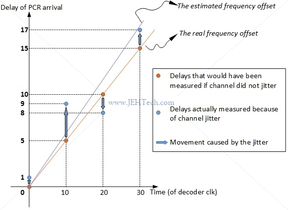
So how do we remove this jitter? (And note this jitter could not only just be from the channel but also either clock). Well, we basically have to guess in an informed way! A basic low pass filter might do the trick but presumably the real mechanisms implemented by manufacturers are far more complex. At least, for now, we have seen what the challenge of the clock recovery is and how MPEG tries to help solve it by providing the PCR timestamps and the D/PTS timestamps.
PTS v.s. DTS
... Some formats, like MPEG, use what they call "B" frames (B stands for "bidirectional"). The two other kinds of frames are called "I" frames and "P" frames ("I" for "intra" and "P" for "predicted"). I frames contain a full image. P frames depend upon previous I and P frames and are like diffs or deltas. B frames are the same as P frames, but depend upon information found in frames that are displayed both before and after them! ...
... So let's say we had a movie, and the frames were displayed like: I B B P. Now, we need to know the information in P before we can display either B frame. Because of this, the frames might be stored like this: I P B B. This is why we have a decoding timestamp and a presentation timestamp on each frame. The decoding timestamp tells us when we need to decode something, and the presentation time stamp tells us when we need to display something ...
... Presentation time stamps have a resolution of 90kHz, suitable for the presentation synchronization task ...
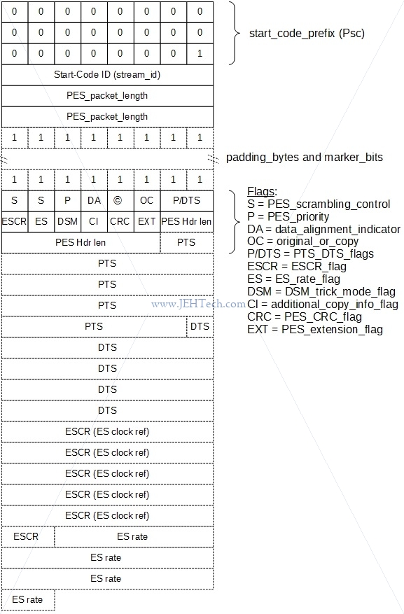
A PES Packet
A Transport Stream Packet
A transport stream packet is shown below. The TS is designed for use in noisy, error-prone, environments. It can include more than one program and each program can have its own independent time base. The splitting up of the PES into 188 byte packets (size can be greater) also adds to the error resistance. All header fields are stored big-endian.
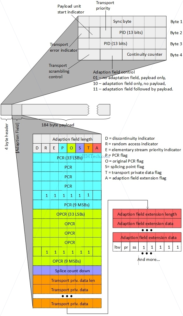
A transport stream packet is at a minimum 188 bytes in length. The first 4 bytes are the header and the remaining 184 bytes are the payload. A PES packet will be distributed across several TS packet layloads.
When a PCR is present the size increases by another 48 bytes, for example, so not all TS packets will be only 188 bytes. In the described base, for instance, the packet size would be 236 bytes.
The continuity counter is a 4-bit field incrementing with each Transport Stream packet with the same PID, unless the adaptation field control of the packet is '00' or '10', in which case it does not increment.
So, for example, one common operation might be to check whether the TS packet contains a PCR. The following test would do it (if you wrote it for real you'd just make it a one-liner!):
bool adaption_field_length_valid = false;
bool adaption_field_contains_pcr = false;
bool adaption_field_present = (raw_ts_packet[3] & 0x20)

if (adaption_field_present) {
   adaption_field_length_valid = (raw_ts_packet[4] > 0);
   if(adaption_field_length_valid)
      adaption_field_contains_pcr = raw_ts_packet[5] & 0x10;
}

if (adaption_field_contains_pcr) {
   // raw_ts_packet[6] to raw_ts_packet[10] and
   // raw_ts_packet[11] & 0xC0 >> 6
}
One of the most important fields is the PID. PIDs are unique identifiers, which, via the Program Specific Information (PSI) tables, the contents of the TS data packet. Some PIDs are reserved:
| Program Association Table | TS-PAT | 0x0000 |
| Conditional Access Table | TS-CAT | 0x0001 |
From the root PID (0x0000), known as the Program Association Table (PAT), we can find the Program Map Table (PMT), which
gives a list of programs for this TS. From the PMT we can in turn find each ES associated with that program.
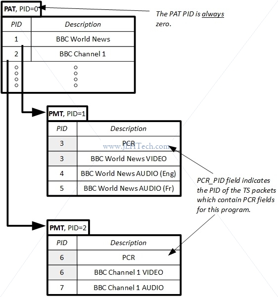
Other PSI tables are also located via the PAT, such as the Conditional Acess Table (CAT) and Network Information Table (NIT). Consult the standard for info on these tables... too much to write here.
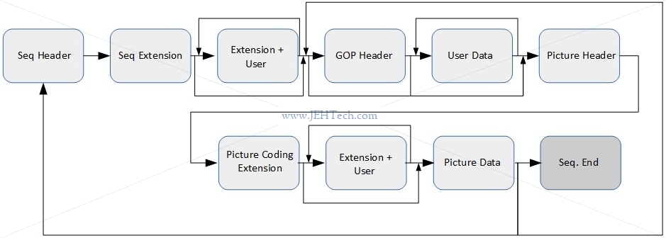
Video Elementary Streams
A video elementary stream (ES) is laid out as a series of sequence headers followed by a series of other optional, variable sized headers and data until the actual picture data. The actual header structures and sequences in which the header data must be parsed is quite detailed so I don't think it is worth replicating here: just gotta go through the standard which lays down the structure very clearly. Just as an idea, here is a 30,000 foot view of one picture sequence:
Meh, okay here are a few of the header formats, but not all of them by an means!
| Start Codes |
| Name | Code |
| picture_start_code | 0x00 |
| slice_start_code | 0x01 – 0xAF |
| user_data_start_code | 0xB2 |
| sequence_header_code | 0xB3 |
| sequence_error_code | 0xB4 |
| extension_start_code | 0xB5 |
| sequence_end_code | 0xB7 |
| group_start_code | 0xB8 |
| system_start_code | 0xB9 – 0xFF |
| Sequence Header |
| Field Name | Bits |
| sequence_header_code | 32 |
| horizontal_size_value | 12 |
| vertical_size_value | 12 |
| aspect_ratio_information | 4 |
| frame_rate_control | 4 |
| bit_rate_value | 18 |
| marker_bit | 1 |
| vbv_buffer_size_value | 10 |
| contrained_parameters_flag | 1 |
| load_intra_quantiser_matrix | 1 |
| if (load_intra_quantiser_matrix): | |
| intra_quantiser_matrix | 8*64 |
| load_non_intra_quantiser_matrix | 1 |
| if (load_non_intra_quantiser_matrix): | |
| load_non_intra_quantiser_matrix | 8*64 |
| next_start_code | |
| Sequence Extension |
| Field Name | Bits |
| extension_start_code | 32 |
| extension_start_code_identifier | 4 |
| profile_and_level_indication | 8 |
| progressive_sequence | 1 |
| chroma_format | 2 |
| horizontal_size_extension | 2 |
| vertical_size_extension | 2 |
| bit_rate_extension | 12 |
| marker_bit | 1 |
| vbv_buffer_size_extension | 8 |
| low_delay | 1 |
| frame_rate_extension_n | 2 |
| frame_rate_extension_d | 5 |
| next_start_code | |
| GOP Header |
| Field Name | Bits |
| group_start_code | 32 |
| time_code | 25 |
| closed_gop | 1 |
| broken_link | 1 |
| next_start_code | |
| Picture Header |
| Field Name | Bits | |||||||||
| picture_start_code | 32 | |||||||||
| temporal_reference | 10 | |||||||||
picture_coding_type
|
3 | |||||||||
| vbv_delay | 16 | |||||||||
| if (picture_coding_type is P or B) | ||||||||||
| full_pel_forward_vector | 1 | |||||||||
| forward_f_code | 3 | |||||||||
| if (picture_coding_type is B): | ||||||||||
| full_pel_backward_vector | 1 | |||||||||
| backward_f_code | 3 | |||||||||
| while (nextbits() is '1'): | ||||||||||
| extra_bit_picture with value '1' | 1 | |||||||||
| extra_information_picture | 8 | |||||||||
| extra_bit_picture with value '0' | 1 | |||||||||
| next_start_code | ||||||||||
One interesting field is the temporal_reference field in the picture header. As will note in a bit, the coded order and display order are different. The
temporal_reference tells the decoder where in this sequence the frame lies in terms of its display order.
Frame Types
There are three types of pictures that use different coding methods:
- Intra-coded (I) pictures are coded using information only from themselves. This means that an I frame can be decoded independently of any other frame. They provide a start point from which future predictively decoded frames can be decoded. Each I-frame is divided into 8x8 pixel blocks, each block being placed in a 16x16 block called a macroblock.
- Predictive-coded (P) use motion compensated prediction from a past reference frame/field: motion vectors for picture blocks. This means that to decode a P frame you need another frame as reference from which you can derive the P frame. You cannot independently decode a P frame. A P frame can be used as the reference for a later P frame (P frames can be the basis for future prediction).
- Bidirectionally predictive-coded (B) pictures use motion compensated prediction from past and/or future reference frames. Like a P frame, a B frame cannot be independently decoded. B frames are not used as a reference for future prediction.
This relationship is shown below:
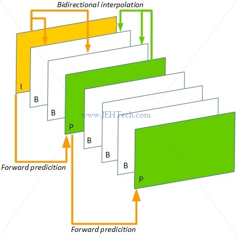
In general the amount of compression that each frame gives increases from I to B. Because the I frame is used as the basis from which we can decode a P frame - we use the I frame + motion compensation - the I frame has the least compression as the quality of the subsequent P and B frames depend on it. B frames offer the most compression.
Interestingly, because B frames exist, the sequence of frames output by an encoder will not likely be the order in which they are presented to the end viewer. The frames are output in stream order, which is the order in which the decoder must decode them.
 For example, imagine you have the following frame display order: I1 P1 B1 P2. In order to encode
frame B1, the encoder needs both frames P1 and P2 as B1 is a predicated frame based on the
contents of the past frame P1 and the future frame P2. Thus the stream
order will be I1 P1 P2 B1.
For example, imagine you have the following frame display order: I1 P1 B1 P2. In order to encode
frame B1, the encoder needs both frames P1 and P2 as B1 is a predicated frame based on the
contents of the past frame P1 and the future frame P2. Thus the stream
order will be I1 P1 P2 B1.
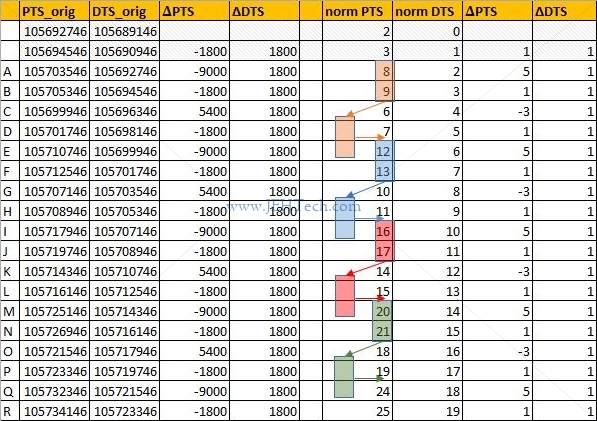
To look at this in "real life" I've loaded some random TS file into MPEG-2 TS packet analyser and read out, from the start of the file, the DTS/PTS timestamps for the first few video frames. Put the values into a spreadsheet, shown to the left (or above depending on your window size and how contents have re-flowed).
I've "normalised" the original timestamps to make them more readable. I've taken the first DTS value and subtracted that from all PTS and DTS values, which I've then divided by 1800. You can see that the DTS increments monotonically and linearly because the frames are transmitted in decoded order, not display order. It is for this reason that you can see the PTS values move around.
The highlighted boxed show how groups of frames are displayed in a different order to the order in which they are decoded. You can see they are decoded before they are displayed. This implies that the frames after them in the TS strean rely on their contents. This implies that the 2 frames following each highlighted box are B frames because they rely on a frame in the future. So, we can infer that frames 6; 10; 14; 18 and so on are B frames. The frames 7; 11; 15; 19 could also be B frames, but they could also be I frames.
So we can distinguish, just from the frame ordering, which frames are B frames. But, we can only do this for a small subset, the rest could be any type. Luckily, each frame has information embedded in it's header that tells us what type it is. This discussion was really just to illustrate the re-ordering :)
Groups Of Pictures (GPS) & Coded Video Sequences (CVS)
The definition of a GOP is easily found on Wikipedia and aplies mostly to H.264. Apparently it is replaced by CVS in H.265 [Ref].
A group of pictures, or GOP structure, specifies the order in which intra- and inter-frames are arranged. The GOP is a collection of successive pictures within a coded video stream. Each coded video stream consists of successive GOPs, from which the visible frames are generated. Encountering a new GOP in a compressed video stream means that the decoder doesn't need any previous frames in order to decode the next ones, and allows fast seeking through the video.
Another nice definition is:
The GOP is, as its name shows, a group of frames arranged in a specific order (I-frames, B-frames and P-frames in case of the H.264/AVC standard). The coded video stream is actually a succession of GOPs of a specific size (e.g 8 or 12 frames, which is set in the header of the standard).
A GOP starts always with an I-frame (Intra coded frame or reference frame) also called "key frame". The size of the GOP is the distance between two consecutive I-frames (e.g IBBPBBPBBPBBI means that the size of the GOP is 12).
To extract GOP from a coded video, you should look at the ffmpeg documentation. One solution could be:
ffmpeg -i INPUT.mp4 -acodec copy -f segment -vcodec copy -reset_timestamps 1 -map 0 OUTPUT%d.mp4[This] will split your input mp4 video into a series of numbered output files starting each with an I-frame.
I have some confusion over wheter CVS is new to H.265 as it appears in the book High Efficiency Video Coding", which is H.264. To quote:
A video of a given number of picutures may be partitioned into one or multiple coded video sequences ... Each CVS can be decoded independently from over coded video sequences that may be contained in the same bitstream ...
... The coding structure comprises a consecutive set of pictures in the sequence with a specific coding order and defined dependencies between the included pictures. The full video sequence may be represented by periodic reprition of this coding structure. The set of pictures that is comprised in the coding structure is ofter called a Group of Pictures (GOP)...
SCTE-35: Advertisment insertion opportunities
SCTE-35 is a standard to signal an advertisement (ad) insertion opportunity in a transport stream ... Ads are not hard coded into the TV program. Instead, the broadcasters insert the ad to the time slot on the fly. This allows broadcasters to change ads based on the air time, geographic location, or even personal preference ... Analog broadcasting used a special audio tone called DTMF to signal the ad time slot. In digital broadcasting, we use SCTE-35 ...
... SCTE-35 was originally designed for ad insertion. However, it turned out to be also useful for more general segmentation signaling ...
The Different Standards: MPEG-2/4, H.264...
https://stackoverflow.com/questions/10477430/what-is-the-difference-between-h-264-video-and-mpeg-4-video
https://wolfcrow.com/blog/understanding-mpeg-2-mpeg-4-h-264-avchd-and-h-265/
https://wolfcrow.com/blog/what-is-a-video-container-or-wrapper/
Audio
Surround Sound, Audio Mixing
Links to make notes on:
https://documentation.apple.com/en/logicpro/usermanual/index.html#chapter=39%26section=2%26tasks=true
http://www.dolby.com/us/en/technologies/a-guide-to-dolby-metadata.pdf
http://www.dolby.com/us/en/guide/surround-sound-speaker-setup/5-1-setup.html
https://en.wikipedia.org/wiki/Audio_mixing_(recorded_music)#Downmixing
The abbreviations used for surround sound channels are as follows [Ref] [Ref] [Ref]:
| Abbreviation | Meaning |
| L | (Front) Left |
| Lc | Left Center |
| C | Center |
| Rc | Right Center |
| R | (Front) Right |
| Lm | Left Mid |
| Rm | Right Mid |
| Ls | Left Surround (Rear Left) |
| S | Surround (Rear Center) |
| Rs | Right Surround (Rear Right) |
| LFE | Low Frequency Effects |
| Lvh | Left Vertical Height |
| Rvh | Right Vertical Height |
| Lrs | Left Rear Sound |
| Rrs | Right Rear Sound |
| Bsl | Back Surround Left |
| Bsr | Back Surround Right |
You will also sometimes get the abbreviation 3/2 surround. This means the configuration uses three front channels (L, R, C) and two rear or surround channes (Ls, Rs) [Ref].
TODO: Calify the above and associated with 5.1, 7.1 etc etc
AES Audio
Specification of the Digital Audio Interface (The AES/EBU interface), Third Edition, EBU, 2004. -- Warning: the channel status word appears to wrong in this document as they've mis-labelled the bytes and there are one too many bytes in it! Using Wikipedia info instead!
Engineering Guidelines: The EBU/AES Digital Audio Interface, J. Emmett, EBU, 1995.
In its original design AES was made to carry "two channels of periodically sampled and linearly represented audio", i.e., LPCM data. However, AES can carry compressed audio data instead, for which an extension to the standard was made.
AES is a sequence of blocks, where each block is composed of 192 frames: When LPCM audio is used the frequency at which AES frames occur is the same as the sampling rate of the PCM audio.
Each of these frames has two 32-bit subframes, one for each of the two audio channels. Each subframe is meant to be one LCPM sample. It contains at most 20 or 24 bits of audio data and the rest if the bits form part of other information structures that are spread across the 192 subframes. I.e., these structures are created by appending each bit from the 192 subframes into one data block.
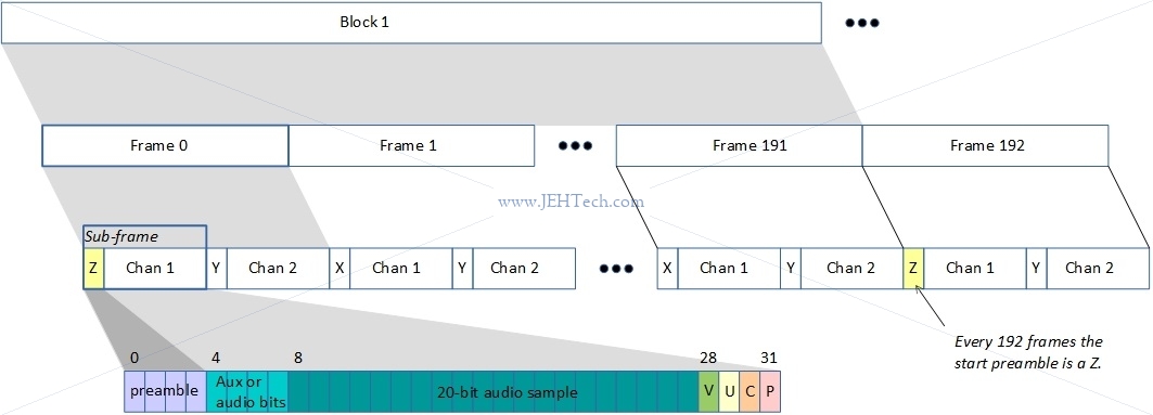
As said, "other information" structures are spread across the 192 subframes. If you take the C bit from the first subframe for channel A as bit 0 of the channel status data, and the C bit from the 192th subframe for channel A as bit 192 of the channel status data, you construct the channel status message. This message carries information associated with the audio signal and is shown below.

As mentioned, AES frames can carry compressed data. When this is the case bit 1 of the channel configuration message indicates whether the audio samples represent linear PCM samples or "something else". When this bit is 0, the samples are LPCM, when it is 1, the samples are "something else". This usually means compressed audio data conforming to some standard, for example Dolby audio etc. The SMPTE standard 337M-2000 describes how not-PCM-audio-data can be inserted into an AES3 packet stream. One example of not-PCM-audio-data is timestamp data used to sync audio with video.
When transmitting not-PCM-sample-data there are two modes available.
- Frame mode: here the audio bits from a frame's two subchannels are combined to give a 48-bit chunk of data.
- Subframe mode: the channels are treated independently.
Audio Standards
MP3 and AAC Explained, K. Brandenburg.
Audio Quality Measures
Total Harmonic Distortion Plus Noise (THD+N)
Versus frequency and versus level.
Frequency Response
Power vs. Time
Dynamic Range
Spectrum Average
Dialog Normalization
FFMPEG
See the docs!
ffmpeg
Intro
General command is:
ffmpeg [global_options] {[input_file_options] -i input_url} ... {[output_file_options] output_url} ...
This is how options like -f can say that they force either the input or output file type: whether
it forces input or output depends whether it appears before the -i or not.
Very useful is to use "-hide_banner" in command lines to get
rid of version info (quite large) in output. Note the UNDERSCORE (not hyphen). To make it super quiet
use the option -loglevel panic as the first command line argument.
Extract Frames
To extract each frame of a video file as an individual picture run the following. FFMPEG parses the output
(printf-like) string and understands from it what you are trying to do.
It will name the frames frame_00001, frame_00002 and so on.
ffmpeg -i <your-input-file> "frame_%05d.png"
You can use other options to output just specific frames too...
ffmpeg -i <your-input-file> -ss 00:00:00:00.000 -vframes 1 <name-of-output-file>
... where -vframes sets the number of video frames to output and -ss sets the start time offset.
Or, lets say you want to output some number of frames from a specific time, you could write....
ffmpeg -i <your-input-file> -ss 00:01:11.123 -vframes 10 "frame_%02d.png"
Or, do the same but not for 10 frames, just for 5 seconds...
ffmpeg -i <your-input-file> -ss 00:01:11.123 -t 5 "frame_%02d.png"
If you don't want the full frame quality you can also scale the output images
and even change them to grey scale if space is an issue. Use the switch
-s widthxheight, e.g., 192x168. You can also use the
-vf scale=w:h. The
scale
parameter is neat because if
you want to keep the same aspect ratio you can just set one of either the width
or height to -1. You can even use refer to the input scale using the
variables ih, for input height and iw, for input
width. Eg, -vf scale=iw/4:-1.
To grayscale use the switch -pix_fmt gray (use the command
ffmpeg -pix_fmts to view avilable formats).
ffmpeg -i <your-input-file> -vf scale=192:-1 -pix_fmt gray "frame_%05d.png"
To extract a specific audio channel from a video file use the following. FFMPEG will create
the type of file you request via the extension. Normally use .wav.
ffmpeg -i <your-input-file> -map 0:2 <name-of-output-file>
The -map option is used for manual control of stream selection in each output file.
Filtering is
done via to -vf option. For example to output one image every I-frame:
ffmpeg -i input.flv -vf "select='eq(pict_type,PICT_TYPE_I)'" -vsync vfr thumb%04d.png
Modify Bitrates
One thing I wanted to do was to be able to artifically increase the bit depth of a WAV file. This doesn't get you better resolution note! You still have the original quantisation error from the lower bit depth. It just enabled me to compare it more easily with another WAV file of differing bit depth.
ffmpeg -acodec pcm_s32le output-file.wav -i input-file.wav
The parameter acodec sets the output audio codec to be used.
Cut out sections
To cut out a section of a video and drop audio, use the following:
ffmpeg -ss 00:00:20 -i [INPUT FILE] -c copy -an -t 00:00:10 [OUTPUT_FILE]
# -ss 00:00:20 - Start 20 seconds in to the video. format is HH:MM:SS
# -c - copy the video i.e don't decode/encode
# -an - drop audio
# -t 00:00:10 - Copy 10 seconds
Compression
To compress your video or change its size try the following:
ffmpeg -i <inputfilename> -s 640x480 -b:v 512k <outputfilename>
Duplicate Sources
The following copies one V4L2 source to two other V4L2 loopback devices...
ffmpeg -hide_banner -i /dev/video0 -c copy -f tee -map 0:v "[f=v4l2]/dev/video10|[f=v4l2]/dev/video11"
formats
FFMPEG supports loads of Discover and specify source formats, and can additionally tell you what formats your device supports...
ffmpeg -f v4l2 -list_formats all -i /dev/videoX
ffmpeg -f v4l2 -input_format mjpeg -video_size=1920x1080 -i /dev/videoX ...
To measure the bandwidth taken by a webcam at a desired frame size, for example:
ffmpeg -loglevel panic -hide_banner -f v4l2 -input_format rawvideo -video_size 1920x1080 -i /dev/videoX -c:v copy -f rawvideo - | pv > /dev/null
Complex Filtering
https://stackoverflow.com/questions/35341451/how-to-duplicate-a-mpegts-stream-into-multiple-other-udp-streams-using-ffmpeg
https://ffmpeg.org/ffmpeg-filters.html#scale-1 and https://ffmpeg.org/ffmpeg-filters.html#Examples-93
https://trac.ffmpeg.org/wiki/FilteringGuide
ffprobe
To get information on your video file you can also use ffprobe. To extract
the frame information use:
ffprobe -show_packets -i <your-input-file>
The ffprobe command lets you select streams too...
# Select only audio streams
ffprobe -show_packets -select_streams a -i <your-input-file>

# Select onl video streams
ffprobe -show_packets -select_streams v -i <your-input-file>

# Select only the video stream with index 1
ffprobe -show_packets -select_streams v:1 -i <your-input-file>
Other useful flags include -show_frames, -show_streams,
-show_programs, -count_frames, --count_packets.
For example, to find information of all video streams you could use the following.
Then by looking for the string "id=0x..." you can find
the PIDs for each video stream.
ffprobe -show_streams -select_streams v -i <your-input-file>
Because the PCR values normally get transmitted with the video stream for any
program, you could also use the following and grab, from the program dump,
the string "pcr_pid=xxx", which should match the
"id=..." string in the video stream info dump.
ffprobe -show_programs -select_streams v -i <your-input-file>
CUDA
https://www.nvidia.com/Download/Find.aspx?lang=en-us
https://developer.nvidia.com/ffmpeg
https://developer.nvidia.com/cuda-downloads?target_os=Linux&target_arch=x86_64&target_distro=Ubuntu&target_version=1604&target_type=runfilelocal
https://docs.nvidia.com/cuda/cuda-installation-guide-linux/index.html
V2L2
v4l2-ctl --device=/dev/video0 --info
v4l2-ctl -d /dev/videoX --list-framesizes=<frame-type>  # Get frame type from --list-formats
             --list-formats[-ext]                  # Use to get frame types
             --(get|set)-input
             --list-inputs
             --set-fmt-video
V4L2 Loopback
If you want to catch an arbitrary video stream and make it appear as a V4L device, i.e., appear as /dev/videoX then
you need V4L loopback. It is a kernel module that will create a V4L device that can be fed frame data from any source, which
then can be read back out from the V4L device using the V4L API.
To install V4LLoopback:
sudo apt install $(uname -r)
sudo apt install libelf-dev

git clone https://github.com/umlaeute/v4l2loopback.git
cd v4l2loopback

make
sudo make install

modprobe v4l2loopback [video_nr=...] [card_label=...]
As an example, lets say you want to capture some arbitrary transport stream from a multicast channel and make that stream appear through a V4L interface:
ffmpeg -i udp://239.0.aaa.bbb:port -vcodec rawvideo -pix_fmt yuv420p -threads 0 -f v4l2 /dev/videoX
You may wish to control the format and size of the V4L device's buffer. In this case you might do something like:
sudo v4l2loopback-ctl set-caps "video/x-raw,format=UYVY,width=1280,height=720" /dev/videoX
If you do this, you must change the transcode of the FFMEG instance feeding this V4L buffer.